SPI - Sniffer v1
SPI - Sniffer v1 — The SPI Sniffer driver block is
used to monitor an existing SPI communication setup.
Library
Simulink Real-Time - Speedgoat
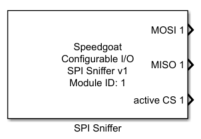
Description
The SPI Sniffer driver block is used to monitor an existing SPI communication
setup.
Ports
Outputs
-
MOSI n (n is the channel number)
The data of the SPI MOSI data line. The width of the output port
vector is defined by the Number of Words per
Frame parameter in the SPI
Configuration tab.
-
MISO n (n is the channel number)
The data of the SPI MISO data line. The width of the output port
vector is defined by the Number of Words per
Frame parameter in the SPI
Configuration tab.
-
Active CS n (n is the channel number)
Indicates which chip select line was active for the last data
transmission. If a value of 0 is read, this means that more than one CS
was active at the same time and that the data may be corrupted. This
port is optional and can be enabled by ticking the Show Active CS Outputs checkbox in the Output Port Configuration tab.
Parameters
Tab: Module setup
-
Configurable I/O Module ID
This parameter associates a code module block with a configurable I/O module setup
block. Set this value to match the Module ID defined in the setup block of the
required configurable I/O module.
-
Channel
The number of the channel which this driver block entity will access. Only one
channel per driver block can be addressed. You can specify channels in the range 1-N
(N = the number of channels implemented in your specific configuration file defined
in the Setup block).
-
Sample Time
Defines the base sample time at which this driver block gets its sample hit. This
parameter can also be set to -1 for inherited
sample time. The units are in seconds.
Tab: SPI Configuration
-
CPOL Vector
The clock polarity parameter:
-
CPHA Vector
The clock phase parameter
-
Number of Bits per Word (Vector)
Defines the size of the words. Valid range is 1 to 32 (see note).
-
Number of Words per Frame (Vector)
Defines the number of words which are sent in a frame. Valid range is
1 to 32 (see note).
![[Note]](images/note.png) | Note |
|---|
The maximum number of bits per SPI transmition is limited to 256 bits.
Therefore, the product of wordSize x frameSize may not be greater than 256.
|
| Note |
|---|
The SPI Sniffer doesn't support variable frame sizes. If a received frame is
smaller than the configured Number of Words per
Frame, the remaining elements will contain old values from
previous transmitions. |
Tab: Input and Output Configuration
-
Show Active CS Output
When this box is checked, the chip select line of the last SPI
transaction will be available in Simulink via a dedicated output port.
If a value of 0 is read at the output port, this means that more than
one CS was active at the same time and that the data may be corrupted.