PWM - Generation v5
PWM - Generation v5 — The PWM generation driver
block configures the PWM generation on the configurable I/O
module
Library
Simulink Real-Time - Speedgoat
Description
The PWM (Pulse Width Modulation) code module provides the following functionality:
Symmetric, asymmetric, single-phase, and multi-phase PWM
generation
Dead band compensation
Frequency-modulated pulse trains
![[Important]](images/important.png) | Important |
|---|
If you are using two blocks, the same channel must not be used twice. If a
different configuration for other channels is required, you must use an
additional driver block in your model. This will not, however, guarantee
that the channels are synchronized. You should use a single PWM block in your model if the PWM signals must be
synchronized; for example, if you need to control a three-phase inverter,
you should use a single block for the three channels, rather than using
three separate blocks (one for each channel). If separate blocks are used, the FPGA registers are updated at different
times (separate PCI write operations, without latching), resulting in
different PWM update times. |
Ports
Depending on which input ports are enabled in the dialog fields of the PWM
generation driver block, this driver block has up to 7 input ports and contains no
output ports. The possible input ports are:
Inputs
-
A-On and A-Off
These ports compare values in seconds and are only active when
Show A Input Port is checked.
-
B-On and B-Off
These ports compare values in seconds and are only active when
Show B Input Port is
checked.
![[Note]](images/note.png) | Note |
|---|
To control PWM A and B with on/off signals, as described above,
PWM Pattern is must be set to
Asymmetric. To use PWM B
independently of PWM A, PWM B Output
is must be set to Independent
of PWM A output. |
-
A-On / B-Off
This port compares values in seconds. The value is applied to A-On and
B-Off (B is the complement of A). This port is only active when
Show A Input Port is
checked.
-
A-Off / B-On
This port compares values in seconds. The value is applied to A-Off
and B-On (B is the complement of A). This port is only active when
Show A Input Port is checked.
| Note |
|---|
To control PWM A and B with on/off signals, as described above,
PWM Pattern is must be set to
Asymmetric. To use PWM B as the
complement of PWM A, PWM B Output
is must be set to The
complement of PWM A output. |
-
C-On and C-Off
These ports compare values in seconds and are only active when
Show C Input Port is checked.
-
Period
The PWM period value in seconds. This port is only active when
Show Period Input Port is checked.
| Note |
|---|
The block user must ensure that the values of A-compare, B-compare and Period-compare are correct in relation to each
other |
-
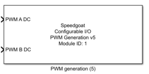
PWM A DC and PWM B DC
The duty cycle to apply on PWM A and B outputs (values between 0.0 and
1.0). These ports are only active when Show A
Input Port is checked for PWM A and Show B Input Port is checked for PWM B.
| Note |
|---|
To control PWM A and B with DC signals, as described above,
PWM Pattern is must be set to
Symmetric. To use PWM B
independently of PWM A, PWM B Output
is must be set to Independent
of PWM A output. |
-
PWM A / #B DC
The duty cycle to apply on PWM A and B outputs (B is the complement of
A). This port is only active when Show A Input
Port is checked.
| Note |
|---|
To control PWM A and B with this signal, as described above,
PWM Pattern is must be set to
Symmetric and PWM B Output is must be set to The complement of PWM A output. |
-
Halt PWM
PWM generation is halted at the next model step after this port is set
to 1. This port is only active when Show PWM
Generation Halt Input Port is checked.
Parameters
Tab: Module setup
-
Configurable I/O Module ID
This parameter associates a code module block with a configurable I/O module setup
block. Set this value to match the Module ID defined in the setup block of the
required configurable I/O module.
-
Channel Vector
A vector of channels this driver block entity will access. You can specify
channels in the range 1-N (N = the number of channels implemented in your specific
configuration file defined in the Setup block). The width of this vector also
defines the subsequent size of some of the following parameters if scalar expansion
applies. With a single block, all the channels of the block are synchronized.
-
Sample Time
Defines the base sample time at which this driver block gets its sample hit. This
parameter can also be set to -1 for inherited
sample time. The units are in seconds.
Tab: PWM generation
-
PWM Phase Vector (s)
A vector of PWM phase values in seconds. The width of this vector must
be equal to the width of the Channel
Vector parameter.
-
PWM Pattern is
The type of PWM signal. There are two possibilities:
In this case, only the duty cycle is configurable with a
value in the range [0.0 to 1.0]
In this case A-On and B-On, and A-Off and B-Off are
freely configurable with a value in the range [0.0 to Initial Period (s)].
-
PWM B Output is
Defines how PWM B output is generated. There are two possibilities:
In this case, the driver itself determines the PWM B
parameters to generate the complement of PWM A output.
In this case, the PWM B output is configured separately.
-
Deadband Duration Vector
Defines how a rising edge on PWM A and on PWM B output is canceled.
The deadband mechanism forces low A/B output until the Deadband Duration
is complete. The units are in seconds. The width of this vector must be
equal to the width of the Channel
Vector parameter.
-
Initial Period Vector (s)
A vector of PWM period values in seconds. The width of this vector
must be equal to the width of the Channel
Vector parameter. This parameter defines the initial pwm
period after the real-time application has been downloaded and
started.
-
Initial Frequency Vector (Hz)
A vector of PWM frequency values in Hz. This vector is read-only and
is calculated from the Initial Period
Vector.
-
Initial PWM A Duty Cycle Vector and Initial PWM B Duty Cycle
Vector
A vector of duty cycle values for PWM A output and PWM B output. The
recommended values are between 0.0 and 1.0, where 0.0 is a duty cycle of
0% and 1.0 is a duty cycle of 100%. The width of these vectors
must be equal to the width of the Channel
Vector parameter.
| Note |
|---|
These parameters are only visible when PWM
Pattern is is set to symmetric. In addition, for Initial PWM B Duty Cycle, PWM
B Output is must be set to Independent of PWM A Output. |
-
Initial A-On Vector and Initial A-Off Vector
A vector of A-On and A-Off values in seconds. The width of this vector
must be equal to the width of the Channel
Vector parameter. The recommended values are between 0
and period (bounds included).
| Note |
|---|
This parameter is only visible when PWM
Pattern is is set to asymmetric. |
-
Initial B-On Vector and Initial B-Off Vector
A vector of B-On and B-Off values in seconds. The width of this vector
must be equal to the width of the Channel
Vector parameter. The recommended values are between 0
and period (bounds included).
| Note |
|---|
This parameter is only visible when PWM
Pattern is is set to asymmetric and PWM B Output
is is set to Independent of PWM
A Output. |
-
Initial C-On Vector and C-Off Vector
A vector of C-On and C-Off values in seconds. The width of this vector
must be equal to the width of the Channel
Vector parameter. The recommended values are between 0
and period (bounds included).
| Note |
|---|
All Initial parameters above are
applied after the real-time application has been downloaded and
started. Depending upon which inputs are used (see Tab: Input Ports Configuration below),
the corresponding initial parameter will be overwritten by the
real-time application from the first step until it stopped. |
-
AB-Output Protection
This protection is used to prevent A and B being high at the same
time. Protection can be configured to be:
Disabled: A and B can be high at the same time
A is forced low when B is high
B is forced low when A is high
Both A and B are forced low if they are both high.
-
Enable the Second Update at Half of the PWM Period
Updates the PWM parameters (A, B and C-On and -Off values) at the
halfway point of the PWM period. The PWM period is always updated once
at the start of the period.
| Note |
|---|
This parameter is no longer visible in PWM 5.7 and subsequent
versions. |
-
Update PWM Generation
Updates the PWM parameters (A, B and C-On and -Off values).
The PWM period is always updated once at the start of
the period. This parameter is only visible as of PWM 5.7.
| Note |
|---|
Values expressed in seconds will be rounded to the FPGA resolution. For
instance, if the FPGA base clock is equal to 75 MHz, then the resolution is
13.33 ns. |
Tab: Triggering
-
Trigger Duration Vector
The duration of a trigger pulse in seconds. This duration can be
different from channel to channel, but the duration is the same for each
trigger selected within one channel. The width of this vector must be
equal to the width of the Channel Vector parameter.
| Note |
|---|
The PWM C and triggers share the same I/O line: the triggers and the PWM C
output are OR wired and then applied to the I/O line of the configurable I/O
module. More than one trigger option can be selected at the same time. |
-
Generate a Trigger at Period Start
When enabled, the PWM code module will emit one trigger pulse when the
period starts.
-
Generate a Trigger at Half of the Period
When enabled, the PWM code module will emit one trigger pulse when the
PWM generation reaches the middle of the defined PWM period.
-
Generate a Trigger at A-On
When enabled, the PWM code module will emit one trigger pulse when the
PWM generation reaches the value of A-On. If the rising edge of the PWM
A output is delayed because of the Deadband
Duration, the trigger is still generated at A-On as
defined by the user and not when the signal effectively changes its
level.
-
Generate a Trigger at A-Off
When enabled, the PWM code module will emit one trigger pulse when the
PWM generation reaches the value of A-Off.
-
Generate a Trigger at B-On
When enabled, the PWM code module will emit one trigger pulse when the
PWM generation reaches the value of B-On. If the rising edge of the PWM
B output is delayed because of the Deadband
Duration, the trigger is still generated at B-On as
defined by the user and not when the signal effectively changes its
level.
-
Generate a Trigger at B-Off
When enabled, the PWM code module will emit one trigger pulse when the
PWM generation reaches the value of B-Off.
| Note |
|---|
Values expressed in seconds will be rounded to the FPGA resolution. For
instance, if the FPGA base clock is equal to 75 MHz, then the resolution is
13.33 ns. |
Tab: Input Ports Configuration
| Note |
|---|
In case any of the below inputs is selected, the real-time application
will overwrite the corresponding Initial
parameters from above from the first step until it stopped. For example, if
you define Initial PWM A Duty Cycle Vector
to 0 and set Show A Input Port, then the
PWM A Duty Cycle will be 0 when the real-time application is downloaded and
started. The value that is applied on the PWM A Duty Cycle input port in the
model will be applied from the real-time application as soon as it is
running. |
-
Show A Input Port
Enables input ports to set the PWM A output during runtime. When
PWM Pattern is is symmetric, a
single input port is used to configure the PWM A output (duty cycle).
The driver itself computes the correct values in order to obtain a
symmetric and centered PWM generation. When PWM
Pattern is is asymmetric, two input ports are available
and they respectively allow A-On and A-Off to be set.
-
Show B Input Port
Enables input ports to set PWM B output during runtime. When PWM Pattern is is symmetric, a single input
port is used to configure the PWM B output (duty cycle). The driver
itself computes the correct values in order to obtain a symmetric and
centered PWM generation. When PWM Pattern
is is asymmetric, two input ports are available and they
respectively allow B-On and B-Off to be set. If the PWM B output is set
to be the complement of the PWM A output, there is no input port
dedicated to PWM B output configuration and in that setup, the driver
will set the correct value on PWM B to generate a complementary signal.
This option is only visible when PWM B output is independent of PWM A
output.
-
Show C Input Port
Enables input ports to set the PWM C output during runtime. PWM C
output is always defined by the C-On and C-Off parameters.
-
Show Period Input Port
Enables the input port to set the PWM period during runtime.
-
Show PWM Generation Halt Input Port
Enables or disables the PWM generation halt input port. PWM generation
is halted at the next model step after this port is set to 1. The
parameter is only visible as of PWM v5.4.
Tab: Offline State
-
PWM Output A is
Defines the PWM A output parameter value loaded when PWM generation is
halted.
-
PWM Output B is
Defines the PWM B output parameter value loaded when PWM generation is
halted.
-
PWM Output C/Trigger is
Defines the PWM C/Trigger output parameter value loaded when PWM
generation is halted.
-
When Model Stops, PWM Generation Halts After Completion of PWM
Period
Controls how PWM generation is halted when the model stops. If
selected, PWM generation continues after the model stops until the
current PWM period is complete, otherwise the PWM generation is halted
when the model stops. The parameter is only visible if the configuration
file supports PWM v5.4.
Tab: Polarity
-
Invert A Output
When checked, the PWM A output is inverted.
| Note |
|---|
The inversion of the signal applies at the very last stage. If PWM
is halted, the defined halt parameter is also inverted. This also
applies to the following two parameters. |
-
Invert B Output
When checked, the PWM B output is inverted.
-
Invert C/Trigger Output
When checked, the PWM C/Trigger output is inverted.