PWM - Capture v1
PWM - Capture v1 — The PWM Capture driver block
records information from the connected PWM signal
Library
Simulink Real-Time - Speedgoat
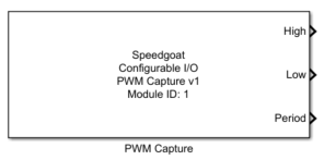
Description
The CAP driver block performs timing measurements (period, high time, low time,
duty cycle) on an input signal.
The signal is recorded between two triggering events. The detection of an event
can be set through the driver (Capture tab).
![[Note]](images/note.png) | Note |
|---|
The FPGA clock frequency and the corresponding time of a tick can be found in the
Setup block. |
Ports
Outputs
-
High
The number of ticks during which the signal was high between two
triggering events.
-
Low
The number of ticks during which the signal was low between two
triggering events.
-
Period
This output returns the number of ticks counted between two triggering
events.
-
DC16
This output returns the duty cycle coded on 16 bits. The range is
between 0.0 and 1.0 (only visible if the configuration file supports
duty cycle calculations).
-
DC8
This output returns the duty cycle coded on 8 bits. The range is
between 0.0 and 1.0 (only visible if the configuration file supports
duty cycle calculations).
-
TOn
This output returns the number of ticks counted between a triggering
event and the rising edge of the input signal (only visible if the
configuration file supports PWM Capture v1.2 or newer).
-
TOff
This output returns the number of ticks counted between a triggering
event and the falling edge of the input signal (only visible if the
configuration file supports PWM Capture v1.2 or newer).
-
Valid Data Flag
This output returns true when two triggering events occur before the
timeout duration (only visible if the configuration file supports PWM
Capture v1.2 or newer).
The output width is defined by the channel count parameter.
DC16 and DC8 outputs are optimized in terms of latency, since the computation is
done on the configurable I/O module.
Parameters
Tab: Module setup
-
Configurable I/O Module ID
This parameter associates a code module block with a configurable I/O module setup
block. Set this value to match the Module ID defined in the setup block of the
required configurable I/O module.
-
Channel Vector
A vector of channels this driver block entity will access. You can specify
channels in the range 1-N (N = the number of channels implemented in your specific
configuration file defined in the Setup block). The width of this vector also
defines the subsequent size of some of the following parameters if scalar expansion
applies. With a single block, all the channels of the block are synchronized.
-
Sample Time
Defines the base sample time at which this driver block gets its sample hit. This
parameter can also be set to -1 for inherited
sample time. The units are in seconds.
Tab: Capture
-
Capture Mode
Defines the nature of a trigger event. Four modes are available:
Each rising edge of the input signal generates a trigger event
Each falling edge of the input signal generates a trigger event
Each rising edge of the additional trigger input signal
generates a trigger event
A trigger event is generated with every model step
-
Capture Timeout Vector
When Capture mode is set to High Transitions
Triggered or Low Transitions
Triggered, the absence of transitions for a duration
greater than the Capture Timeout Vector
will cause the PWM Capture to initiate an internal trigger. Correct
values are in the range 0 to 223 ms. When the Capture Timeout Vector is set to 0, the feature is
disabled. The parameter is only visible if the configuration file
supports PWM Capture v1.2 or newer.
-
Channel Debounce Time
Defines the time in seconds during which the input and the trigger
input signal must be stable before an edge is detected. Defaults to
100e-9 (100 ns).
The range and resolution of the debounce duration depend on the module
frequency that is shown in the Setup block. The Effective Debounce Time therefore indicates the applied
duration at the module level.
To disable debouncing, enter the value 0.
Correct values are in the range 0 to 2^18-1 ticks (e.g., 3.495 ms at a
frequency of 75 MHz). The parameter is only visible if the configuration
file supports PWM Capture v1.12 or newer. The parameter must be a scalar
value that applies to all channels defined in the Channel Vector.
Tab: Input and output port configuration
-
Show High Duration
When this parameter is checked an additional output is available to
read the high duration of the recorded signal between two trigger
events.
-
Show Low Duration
When this parameter is checked an additional output is available to
read the low duration of the recorded signal between two trigger
events.
-
Show Period
When this parameter is checked an additional output is available to
read the total duration between two trigger events.
-
Show Duty Cycle (16 bits)
When this parameter is checked an additional output is available to
read the duty cycle computed by the configurable I/O module and coded on
16 bits. The module will compute the ratio between high duration and the
period. The duty cycle is encoded between 0.0 and 1.0 with an accuracy
of 2-15. Compared to duty cycle computation
within Simulink, one PCI access is saved. When more than one channel is
selected and if these channels are contiguous, the PCI read access is
packed. Two CAP channels can be read in one PCI access. The parameter is
only visible if the configuration file supports duty cycle calculations.
-
Show Duty Cycle (8 bits)
When this parameter is checked an additional output is available to
read the duty cycle computed by the configurable I/O module and coded on
8 bits. The module will compute the ratio between high duration and the
period. The duty cycle is encoded between 0.0 and 1.0 with an accuracy
of 2-7. Compared to duty cycle computation
within Simulink, one PCI access is saved. When more than one channel is
selected and if these channels are contiguous, the PCI read access is
packed. Four CAP channels can be read in one PCI access. This is the
suggested option if maximum performance is required (Minimum I/O
latency). The parameter is only visible if the configuration file
supports duty cycle calculations.
-
Show TOn
When this parameter is checked an additional output is available to
read the time (in ticks) between a trigger event and the rising edge of
the input signal. The parameter is only visible if the configuration
file supports PWM Capture v1.2 or newer.
-
Show TOff
When this parameter is checked an additional output is available to
read the time (in ticks) between a trigger event and the falling edge of
the input signal. The parameter is only visible if the configuration
file supports PWM Capture v1.2 or newer.
-
Show Valid Data Flag
When this parameter is checked an additional output is available to
read the Valid Data Flag. Data Flag is true when the PWM input is
captured within the timeout duration. The parameter is only visible if
the configuration file supports PWM Capture v1.2 or newer.