I/O Sync and PWM Generation
I/O Sync and PWM Generation — The PWM generation driver
block allows for synchronization with selected analog I/O modules and configures
the PWM generation on the configurable I/O module
Library
Simulink Real-Time - Speedgoat
Description
The I/O Sync and PWM (Pulse Width Modulation) Generation code module provides the
following functionality:
![[Important]](images/important.png) | Important |
|---|
If you are using two blocks, the same channel must not be used twice. If a
different configuration for other channels is required, you must use an
additional driver block in your model. This will not, however, guarantee
that the channels are synchronized. You should use a single PWM block in your model if the PWM signals must be
synchronized; for example, if you need to control a three-phase inverter,
you should use a single block for the three channels, rather than using
three separate blocks (one for each channel). If separate blocks are used, the FPGA registers are updated at different
times (separate PCI write operations, without latching), resulting in
different PWM update times. |
Ports
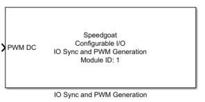
This driver block has one input port and contains no output ports.
Input
-
PWM DC
The duty cycle to apply on the different PWM signals (values between
0.0 and 1.0). This input is commonly a vector signal of the size of the
active PWM channels.
Parameters
Tab: Module setup
-
Configurable I/O Module ID
This parameter associates a code module block with a configurable I/O module setup
block. Set this value to match the Module ID defined in the setup block of the
required configurable I/O module.
-
Number of user PWM channels
Select the number of active user PWM channels to be used together
with the synchronization signals. This number added to the number of
sync channels should not exceed the total number of available channels.
When using synchronization with the IO106, only the first PWM channel
will be used for sync signals. When using synchronization with the
IO132-IO135 family, the first three PWM channels will be used for sync
signals. Note that the selected number of user channels will follow the
sync signals in an ascending order. If your model contains another PWM
block with the same module ID, make sure to not use any channel
twice.
-
Sample Time
Defines the base sample time at which this driver block gets its sample hit. This
parameter can also be set to -1 for inherited
sample time. The units are in seconds.
Tab: PWM generation
-
Desired base PWM period (s)
Defines the base PWM period in seconds. All the generated PWM signals
of the block will try to conform to this period length.
-
Effective base PWM period (s)
This field displays the actual base PWM period in seconds. If the
desired PWM period cannot be output exactly, the value of the actual PWM
base period will be rounded to the nearest possible value.
-
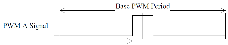
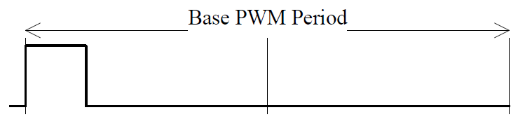
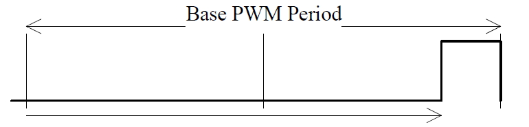
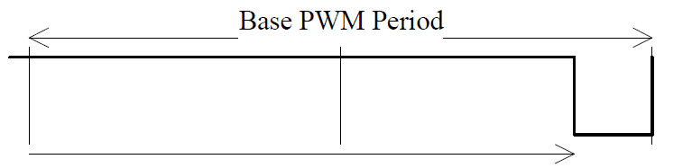
Duty cycle alignment
Defines how the base PWM signal is aligned. There are three
possibilities:
In this case, the PWM impulse is located at the middle of the base
period length

In this case, the PWM impulse is located at the start of the base
period length
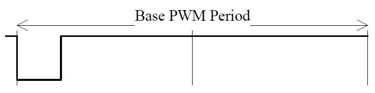
In this case, the PWM impulse is located at the end of the base period
length
-
Deadband Duration Vector
Defines how a rising edge on PWM A and on PWM B output is canceled.
The deadband mechanism forces low A/B output until the Deadband Duration
is complete. The units are in seconds. The I/O Sync and PWM Generation
only accepts a scalar value, valid for all elements of the Channel Vector.
-
Enable the Second Update at Half of the PWM Period
Updates the PWM parameters (A, B and C-On and -Off values) at the
halfway point of the PWM period. The PWM period is always updated once
at the start of the period.
![[Note]](images/note.png) | Note |
|---|
This parameter is no longer visible in PWM 5.7 and subsequent
versions. |
Tab: Intermodule Sync
-
I/O module family
Use this drop down menu to select which Sync format you would like to
output on the sync channels.
-
Sampling mode
In this mode, only one sample is triggered per base sample period. The
Sample position dropdown menu
allows you to select the position of that single sample. Possible
selections are: Start of base PWM
period and Middle of base PWM
period.
In this mode, multiple samples can be triggered per sample period.
Adapt the number with the help of the Number of
samples edit field. If I/O module
family IO132-IO135 is selected, you can additionally
define on which sample the frame should be triggered, by specifying a
number between 1 and the Number of
samples value, in the Frame trigger
position edit field.
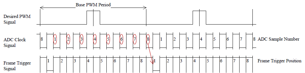
Depicted above is an example of a setting of Number of samples = 8 and Frame
trigger position = 1.
-
Recommended settings
At the bottom of the Intermodule sync
tab, the recommended timing settings for the selected Analog module are
listed, based on the settings defined in the PWM
generation and Intermodule
sync tab.
Tab: Triggering
-
Trigger Duration Vector
The duration of a trigger pulse in seconds. This duration can be
different from channel to channel, but the duration is the same for each
trigger selected within one channel. The width of this vector must be
equal to the width of the Channel Vector parameter.
| Note |
|---|
The PWM C and triggers share the same I/O line: the triggers and the PWM C
output are OR wired and then applied to the I/O line of the configurable I/O
module. More than one trigger option can be selected at the same time. |
-
Generate a Trigger at Period Start
When enabled, the PWM code module will emit one trigger pulse when the
period starts.
-
Generate a Trigger at Half of the Period
When enabled, the PWM code module will emit one trigger pulse when the
PWM generation reaches the middle of the defined PWM period.
-
Generate a Trigger at A-On
When enabled, the PWM code module will emit one trigger pulse when the
PWM generation reaches the value of A-On. If the rising edge of the PWM
A output is delayed because of the Deadband
Duration, the trigger is still generated at A-On as
defined by the user and not when the signal effectively changes its
level.
-
Generate a Trigger at A-Off
When enabled, the PWM code module will emit one trigger pulse when the
PWM generation reaches the value of A-Off.
-
Generate a Trigger at B-On
When enabled, the PWM code module will emit one trigger pulse when the
PWM generation reaches the value of B-On. If the rising edge of the PWM
B output is delayed because of the Deadband
Duration, the trigger is still generated at B-On as
defined by the user and not when the signal effectively changes its
level.
-
Generate a Trigger at B-Off
When enabled, the PWM code module will emit one trigger pulse when the
PWM generation reaches the value of B-Off.
| Note |
|---|
Values expressed in seconds will be rounded to the FPGA resolution. For
instance, if the FPGA base clock is equal to 75 MHz, then the resolution is
13.33 ns. |