IO901/IO902 Usage Notes
IO901/IO902 Usage Notes — Usage information
about the I/O module
Initialize Shared Memory Nodes
To use the IO901/IO902 shared memory I/O module, you must define a node
initialization structure. The I/O modules drivers use MATLAB structures to define
shared memory node initializations. A node initialization structure describes the
shared memory partition and the IO901/IO902 board configuration, including interrupt
configurations.
The initialization can done with an m-file, which is then loaded with your
Simulink model
(see example
io901_io902_init.m). The following usage notes describe the
initialization procedure.
Memory Partitions
For each variable, a partition must be defined. The example below shows how to
define the variables:
Partitions(1).Size = '1';
Partitions(1).Type = 'uint8';

Partitions(2).Size = '2';
Partitions(2).Type = 'double';

Partitions(3).Size = '1';
Partitions(3).Type = 'double';

Partitions(4).Size = '1';
Partitions(4).Type = 'uint8';

Partitions(5).Size = '2';
Partitions(5).Type = 'double';

Partitions(6).Size = '1';
Partitions(6).Type = 'double';
Partitions(6).Address = '0x5000';

Partitions = completepartitionstruct(Partitions,'5565');
For further information, function sscgtpartitionstruct can be used.
Partition = scgtpartitionstruct(Partition);
Nodes
Each shared memory I/O module installed needs to have a "node ID":
Target Machine 1 – Node ID = 1
Node1.Interface.NodeID = '1';
InitiatorNode.Partitions = Partitions;
InitiatorNode = completenodestruct(InitiatorNode,'5565');
Target Machine 2 – Node ID = 2
TargetNode.Interface.NodeID = '2';
TargetNode.Interface.Interrupts.PendingInt1='on';
TargetNode.Partitions = Partitions;
TargetNode = completenodestruct(TargetNode,'5565');
Create a node initialization structure for each I/O module with the help of the
scgtnodestruct command. Type
for a description of the
command.
Create Shared Memory Partitions
To use the IO901/IO902 blocks to Read, or Write data, you must define a partition
structure. The shared memory drivers use MATLAB structures to define shared memory
partitions. A partition structure describes how you want to allocate (or partition)
the shared memory. Speedgoat Target allocates shared memory with bundles of data
that are packed into memory partitions. Create a shared memory structure with the
scgtpartitionstruct command. Type
for a description of the command.
Using the scgtpartitionstruct command at the MATLAB Command
Window, create a default partition structure. For example, type
At the MATLAB Command Window, create a user-defined partition structure.
The easiest way to do this is to create an M-file, partially define a
structure, load that M-file into the MATLAB workspace, and supplement the
resulting structure with a call to the scgtpartitionstruct
function.
For example
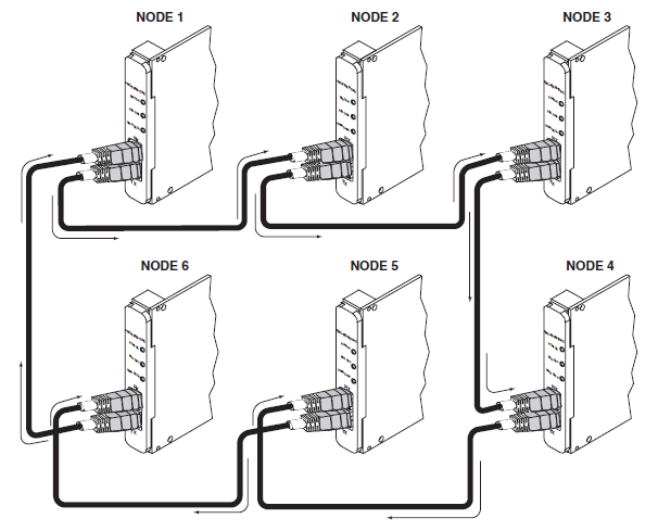
Network Wiring
Each IO901/IO902 port has two fiber optic connections, RX (receive) and TX
(transmit). When connecting two systems, a crossed connection is required. For
networks with several nodes, a ring connection is required.
Using shared memory to synchronize target machines
This section provides information on how to synchronize multiple
real-time target machines using Shared/Reflective Memory on IO901/IO902 I/O modules
and interrupts. The first target machine works as an initiator, and sets the timing
for the other machine(s), using a Network interrupt. This ensures that all the
target machines are completely synchronized, and can access the same variables and
values at the same time.
To use the interrupt mode for synchronization of the target machines, the board
interrupts need to be activated. When initiating the nodes, add the lines in your
initialization procedure:
Unicast interrupt:
Target – Node ID = 2
TargetNode.Interface.Interrupts.UnicastInterrupts = 'on';
Broadcast interrupt:
Initiator – Node ID = 1
InitiatorNode.Interface.Interrupts.ChangeBroadcastInterruptMask = 'yes';
InitiatorNode.Interface.Interrupts.BroadcastInterruptMask = '0xffffffff';
Target – Node ID = 2
TargetNode.Interface.Interrupts.ChangeBroadcastInterruptMask = 'yes';
TargetNode.Interface.Interrupts.BroadcastInterruptMask = '0xffffffff';
After configuring the inizalization structure, the Simulink real-time models can
be run on each target. For the initiatior node, make sure to use a Send Interrupt
block. For more information, refer to block
documentation.
The Simulink real-time model of the target node requires a Speedgoat Interrupt
Block that triggers the application or a subystem. Refer to the block
documentation for more information.
Board Interrupts
The IO901/IO902 board allows you to specify the interrupt sources transmitted and
received between the nodes of the network. You can set these bits through the
Interface.Interrupts field. The Interface Interrupts fields set the
corresponding values on the board. A value of 'nc' does not change the current value
on I/O module. To display the board mode fields, type
These fields have the following values:
Additional board settings
Board Mode
The IO901/IO902 board has a number of modes that you can set through the
Interface.Mode field. The Interface Mode fields set the
corresponding enables on theboard. A value of 'nc' does not change the current value
on the board. To display the board mode fields, type
These modes have the following values:
Board Lasers
The IO901/IO902 board allows you to turn on or off the transmit lasers through the
Interface.Lasers field. The Interface Lasers fields set the
corresponding enables on the board. A value of 'nc' does not change the current
value on I/O module. To display the board mode fields, type
These fields have the following values: