Documentation search search close
CONTENTS
https://www.speedgoat.com/help/slrt/page/icon_documentation.jpg
v10.0.1.x for R2026a
View other versions

IO756 Usage Notes

IO756 Usage Notes — Usage information about the I/O module

Description

This section describes how to configure the EtherNet/IP network.

EDS File

To set up EtherNet/IP communication, you must import the device description files of EtherNet/IP adapters (EDS file) into your EtherNet/IP scanner configuration tool or PLC programming tool (for example, Studio 5000 Logix Designer). Find the EDS file of the IO756 EtherNet/IP Adapter module here:

>> [speedgoatroot, '\sg_blocks\cifx\eds\CIFX-RE EIS V1.1.eds'].

If you use warmstart parameters to simulate an EtherNet/IP adapter of a different vendor, you must import the EDS file of that particular adapter into your scanner configuration tool. The EDS file is generally available on the vendor's website.

Front Plate Description

IO756 PCI and PCIe modules

The IO756 acts as one EtherNet/IP Adapter exclusively. The two RJ45 connectors simply serve to build up a line-based network structure. Plug the cable from the EtherNet/IP Scanner or the previous Adapter into the first socket. Connect the second socket with the next EtherNet/IP Adapter. The LEDs described below indicate the communication status of the single EtherNet/IP Adapter.
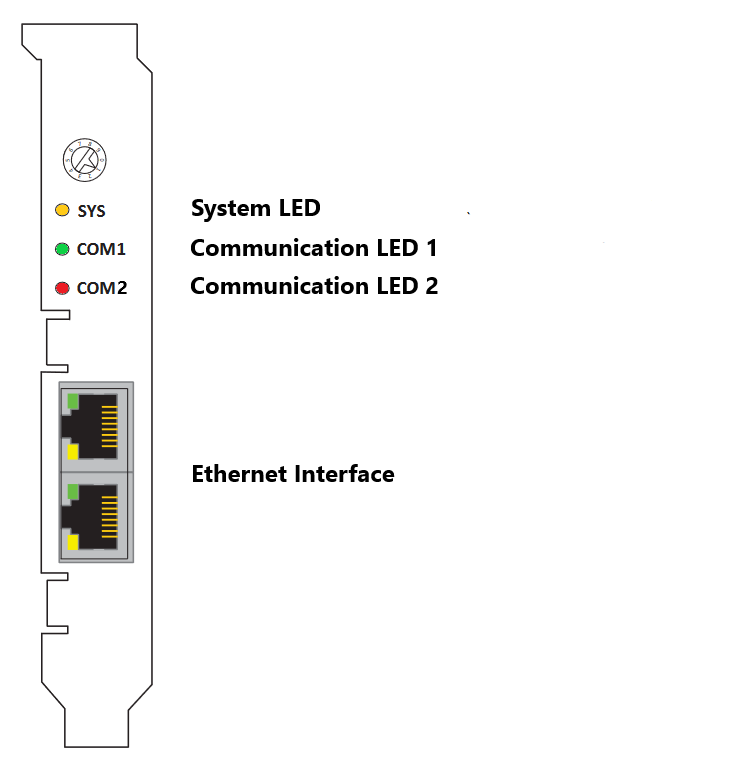
The rotary switch has no functional role.

IO756 mPCIe module
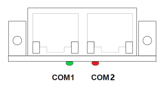
Note that in some real-time target machines, the mPCIe module is reversed; that is, the Error LED appears on the right.

IO756-32 Multi-node simulator

The IO756-32 simulates 32 EtherNet/IP Adapter nodes, split into two clusters with 16 protocol chips each. Within a cluster, the nodes represent a line-based network structure. Build up a combined network by connecting both center sockets. You can use the leftmost or rightmost socket to connect the EtherNet/IP Scanner device. Use the remaining socket to connect an external EtherNet/IP Adapter or another IO756-32 module.

Each node has two LEDs that indicate the communication status.

LED Status Description

LEDColorStateMeaning
SYSGreenOnOperating system running
 Green/YellowBlinkingSecond stage bootloader is waiting for firmware
 YellowOnBootloader netX (= romloader) is waiting for second stage bootloader
 OffOffPower supply for the device is missing or hardware defect
MS/COM1GreenOnDevice operational: The device is operating correctly.
 GreenFlashing (1 Hz) Standby: The device has not been configured.
 Green/Red/GreenFlashing

Self-test: The device is performing its power-up testing. The module status indicator test sequence occurs before the network status indicator test sequence, according to the following sequence:

• Network status LED off.

• Module status LED turns green for approximately 250 ms, turns red for approximately 250 ms, and again turns green (and holds that state until the power-up test has completed).

• Network status LED turns green for approximately 250 ms, turns red for approximately 250 ms, and then turns off (and holds that state until the power-up test has completed).

 RedBlinking (1 Hz)Major recoverable fault: The device has detected a major recoverable fault. E.g., an incorrect or inconsistent configuration can be considered a major recoverable fault.
 RedOnMajor unrecoverable fault: The device has detected a major unrecoverable fault.
 OffOffNo power: The device is powered off.
NS/COM2GreenOnConnected: An IP address is configured, at least one CIP connection (any transport class) is established, and an Exclusive Owner connection has not timed out.
 GreenFlashing (1 Hz)No connections: An IP address is configured, but no CIP connections are established, and an Exclusive Owner connection has not timed out.
 Red/Green/OffFlashingSelf-test: The device is performing its power-up testing. Refer to description for module status LED self-test.
 RedBlinking (1 Hz)Connection timeout: An IP address is configured and an Exclusive Owner connection for which this device is the target has timed out. The network status indicator returns to steady green only when all timed out Exclusive Owner connections are reestablished.
 RedOnDuplicate IP: The device has detected that its IP address is already in use.
 OffOffNot powered, no IP address: The device does not have an IP address (or is powered off).

Note that only the IO756 PCI and PCIe modules have the SYS LED. This LED does not feature on the IO756 mPCIe module and the IO756-32 multi-node simulator.

Status Codes

For the list of status codes, please refer to Status Codes for Protocols Supported with the IO64x/IO75x Modules.