IO756 - Setup v2
IO756 - Setup v2 —
Configure the IO756 I/O module
Library
Simulink Real-Time - Speedgoat
Description
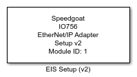
The IO756 Setup block configures the EtherNet/IP
adapter protocol stack of the related I/O module and enables the send and receive
blocks to exchange data with the remote EtherNet/IP scanner.
Your model can contain only one Setup block
for each I/O module in your target machine.
Ports
This driver block has no input or output ports.
Parameters
General
- Module ID
The Module ID has two functions:
It logically connects the Setup block and its I/O blocks
It also informs the auto-search feature of the PCI Slot parameter. If only
one I/O module of this family is installed, the Module ID must be set to
1. To see how each I/O module maps to a
Module ID, use this Speedgoat API:
speedgoat.getIoInterfaces("TargetName", "mySpeedgoat")
This Setup block belongs to two families of I/O modules that use the same hardware
for multiple protocols. Across both families, the Module ID must be unique.
IO64X/IO75X (single-node modules): IO641,
IO642, IO643, IO644, IO750, IO751, IO752, IO753, IO754, IO755, IO756,
IO758
IO64X-32/IO75X-32 (multi-node modules):
IO642-32, IO752-32, IO754-32, IO756-32
If the PCI Slot parameter is set to -1
(auto-search), the Module ID must be in the range 1:n, where 'n' cannot be larger
than the number of modules of this type installed in the target machine. Not all
installed I/O modules need to be used.
To use this Setup block with a multi-node I/O module (IO75X-32 family), the Module
ID must be defined as a two-element vector. The second vector element is the
sub-module ID. It describes the specific node (1:32) within the I/O module. The 32
nodes are internally connected to form two linear networks (daisy-chain), where the
first and the last node of both chains are externally accessible. If one node is not
configured (has no Setup block), the chain terminates at this point. The sub-module
IDs must therefore start at node 1, 16, 17 or 32 and not have any gaps.
![[Note]](images/note.png) | Note |
|---|
When using I/O modules of both families simultaneously (single-node and
multi-node I/O modules), always use explicit addressing in the PCI Slot parameter. Ignore the Module IDs returned by
the getIoInterfaces function and instead assign unique Module IDs accross all
modules used. |
-
PCI Slot (-1: auto-search)
There are two approaches for mapping the block to a specific I/O
module installed in your target machine. All modules of the same
family (see Module ID above) must be configured using the same
method.
- Auto-Search: with the default value -1 the I/O module will be
automatically located in the target machine. If you have
multiple modules of the same family, the Module ID (first
vector element for a multi-node module) defines which module
is associated with this block. To see how each I/O module
maps to a Module ID, use this Speedgoat API:
speedgoat.getIoInterfaces("TargetName", "mySpeedgoat") - Explicit Addressing: to explicitly define the logical
address of the I/O module in the target machine, you can
provide the PCI bus and slot numbers as a vector: [bus,
slot]. To determine these numbers, run the following command
in the MATLAB command window:
speedgoat.getIoInterfaces("TargetName", "mySpeedgoat", "Advanced", true)Note
that the PCI address can change whenever an I/O module is
added or removed. Usually, auto-search is the best option.
-
Configuration Mode
Depending on this parameter, the Connection tab shows different parameters.
Simple: In the Connection tab, you can define one
input assembly and one output assembly of individual lengths. In
addition, the protocol stack automatically creates additional
assemblies as well as a pre-defined set of connection points
according to the CIFX-RE EIS V1.1.eds file, which you can locate
by calling the following function from the MATLAB® command line:
which('CIFX-RE EIS V1.1.eds')
This mode is used for prototyping purposes where you want to
exchange individual signals with remote EtherNet/IP scanner
devices.
Extended: The user can define
all assemblies and connection points according to any EDS file.
This mode is used for simulation purposes where the remote
scanner expects particular EtherNet/IP devices to exist in the
network.
IP
This tab includes the module's IP settings required for TCP and UDP
communication
-
IP Address
IP address in the format xxx.xxx.xxx.xxx
Data Type:
character array
Example:
'10.10.48.101'
-
Network Mask
Network mask in the format xxx.xxx.xxx.xxx
Data Type:
character array
Example:
'255.255.0.0'
-
Gateway
Gateway in the format xxx.xxx.xxx.xxx
Data Type:
character array
Default:
'0.0.0.0'
Ident
The following parameters define the so-called electronic key of the
EtherNet/IP adapter. During connection, EtherNet/IP scanners check whether the
values match the expected adapter. Scanner devices can usually be configured to
check all, some, or none of the electronic key values. The default values
originate from the CIFX-RE EIS V1.1.eds file. For prototyping purposes, use this
file to introduce the adapter to the scanner and do not change the identity
parameters in the block mask. For simulation purposes, enter the electronic key
values of the device (EDS file) you want to simulate.
-
Vendor ID
Vendor ID in the range 0 to 65535
Data Type:
integer
Default:
283
-
Product Type (CIP Device Type)
Product type in the range 0 to 65535
Data Type:
integer
Default:
12
-
Product Code
Product code in the range 1 to 65535
Data Type:
integer
Default:
257
-
Minor Revision
Minor revision in the range 1 to 255
Data Type:
integer
Default:
1
-
Major Revision
Major revision in the range 1 to 127
Data Type:
integer
Default:
1
-
Device Name
Name of the device
Data Type:
array of less than 31 characters
Default:
'CIFX RE/EIS'
Connection
This tab includes the parameters required for EtherNet/IP implicit messaging.
In contrast to explicit messaging, implicit messaging is based on a
consumer-producer architecture where a fix range of process data is cyclically
transferred via UDP. The EtherNet/IP scanner consumes data from the EtherNet/IP
adapter (input data) and produces data to be sent to the adapter (output
data).
The scanner (originator) connects to the adapter (target) choosing one of the
connection paths the adapter provides. Available connection paths are described
in the adapter's EDS file. One connection path consists of three connection
points:
Each connection point is linked to an assembly instance. An assembly has a
specific length and represents specific signals in the adapters input process
data area, output process data area or configuration data area. The adapter's
input, output and configuration assemblies are described in the EDS file. The
file also shows the links between the assemblies and connection points.
When the scanner/originator connects to a specific connection path of the
adapter/target,
the scanner connects to the input connection point to consume data
from the input assembly the connection point refers to. Input data is
data the adapter acquires from the sensor level of a plant. In Simulink®,
input data is data you write using the IO756 Send block
the scanner connects to the output connection point to provide data to
the output assembly the connection point refers to. Output data is data
the adapter provides to the sensor/actuator level. In Simulink, output
data is data you read using the IO756 Receive block
the scanner connects to the configuration connection point to write
parameters of the adapter. In Simulink, configuration data is data you
read using the IO756 Receive block
Connection points do not necessarily need to link to an assembly. So-called
"exclusive owner" connection paths usually have linked input and output
connection points and optional configuration points. Listen-only connections
usually have only the input connection point linked with a listen-only
assembly.
Depending on the Configuration parameter, the
Connection tab shows different
parameters.
-
Simple Configuration
According to the CIFX-RE EIS V1.1.eds file, the protocol stack
creates one input assembly, one output assembly, one input-only
assembly (ID 0xC1) and one listen-only assembly (ID 0xC0) as well as
the following connection paths:
Exclusive owner: The input and output connection points
are linked to the input and output assemblies
Listen-only: The input connection point is linked to the
input assembly. The output connection point is linked to the
listen-only assembly.
Input-only: The input connection point is linked to the
input assembly. The output connection point is linked to the
input-only assembly.
No configuration assemblies are created by the protocol stack and
no additional assemblies can be defined by the user.
The values entered in the following parameters must match the
corresponding values in the EDS file that you use to register the
device in the scanner configuration.
-
Input Assembly - Instance ID
Enter a unique ID for the input assembly in the range 1 to
65535.
-
Input Assembly - Number of Bytes
The data length of the input assembly. The value must
range between 0 and 1200 and must match the Number of Bytes parameter of the
Send block.
-
Input Assembly - Transfer Format
Select whether the EtherNet/IP frame header should include
additional control/status information.
-
Output Assembly - Instance ID
Enter a unique ID for the output assembly in the range 1
to 65535.
-
Output Assembly - Number of Bytes
The data length of the output assembly. The value must
range between 0 and 1200 and must match the Number of Bytes parameter of the
Receive block.
-
Output Assembly - Transfer Format
Select whether the EtherNet/IP frame header should include
additional control/status information.
-
Extended Configuration
All assemblies and connection paths must be defined by the
user.
-
Assemblies
Pass a vector of struct to this parameter to define and
configure the module's assemblies. The required struct
elements are:
ID: The instance ID of the assembly
Type: Possible values are
'Output' (0)
'Input' (1)
'Config' (2)
'InputOnly' (3)
'ListenOnly' (4)
You can enter either the character
array or the number.
Length: The data length of the assembly
Format: Select whether the EtherNet/IP frame
header should include additional control/status
information (0) or not (1). Not considered for
configuration assemblies
You can create the struct in the base workspace, the model
workspace or in a data dictionary and pass the variable name
to the mask parameter. Example:
Assemblies(1).ID = 101;
Assemblies(1).Type = 'Output';
Assemblies(1).Length = 11;
Assemblies(1).Format = 0;

Assemblies(2).ID = 100;
Assemblies(2).Type = 'Input';
Assemblies(2).Length = 15;
Assemblies(2).Format = 0;
As an alternative, you can directly define the struct in
the mask parameter. Example:
[struct('ID',101,'Type','Output','Length',11,'Format',0), ...
 struct('ID',100,'Type','Input','Length',15,'Format',0)]
-
Connections
Pass a vector of struct to this parameter to define and
configure the module's connection paths. The required struct
elements are:
InputID: Enter the instance ID of the assembly
you want to link to the input connection
point
OutputID: Enter the instance ID of the
assembly you want to link to the output connection
point
ConfigurationID: Enter the instance ID of the
assembly you want to link to the configuration
connection point. Enter 0 if no configuration
assembly is defined
Type: Possible values are
'ExclusiveOwner' (0)
'ListenOnly' (1)
'InputOnly' (2)
You can enter either the character
array or the number.
You can create the struct in the base workspace, the model
workspace or in a data dictionary and pass the variable name
to the mask parameter. Example:
Connections(1).InputID = 101;
Connections(1).OutputID = 100;
Connections(1).ConfigID = 0;
Connections(1).Type = 'ExclusiveOwner';
As an alternative, you can directly define the struct in
the mask parameter. Example:
[struct('InputID',101,'OutputID',100','ConfigID',0,'Type',0)]