IO754 Usage Notes
IO754 Usage Notes — Usage information about the
I/O module
Introduction to Modbus TCP
A Modbus TCP client usually sends requests to a server to read and write data of
specific areas. A server usually manages 4 areas:
Coils (bit values the client can read and write)
Discrete Inputs (bit values the client can only read)
Holding Registers (word values the client can read and write)
Input Registers (word values the client can only read)
The client request consists of
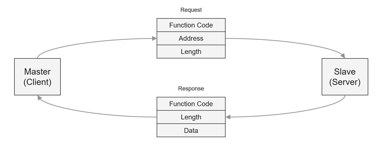
For read requests, the server sends a response to the client which contains the
original function code and the data which has been requested. For write requests the
server sends a simple confirmation containing the function code.
The following function codes are supported by Speedgoat ModbusTCP modules
FC1 (Read Multiple Coils)
FC2 (Read Multiple Discrete Inputs)
FC3 (Read Multiple Holding Registers)
FC4 (Read Multiple Input Registers)
FC5 (Write Single Coil)
FC6 (Write Single Holding Register)
FC15 (Write Multiple Coils)
FC16 (Write Multiple Holding Registers)
Depending on the data area, there are two types of address and length
information:
Coils/Discrete Inputs: Bit address, Number of bits (bit-based)
Holding Registers/Input Registers: Word address, Number of words (16
bit-based)
In the following tables you can see how the four data areas are structured and how
bit- and word-addressing works. The Modbus addresses 0XXXX, 1XXXX, 3XXXX and 4XXXX
are still commonly used to label ModbusTCP registers. They have been taken over from
ModbusRTU but serve no purpose in ModbusTCP addressing.
Operation Modes
The IO754 I/O module manages the four data areas as described in the introduction.
The IO754 Simulink block library supports two modes to access the data:
Select the mode in the IO754 Setup block.
Message Mode
Use IO754 Message blocks to access Coils, Discrete Inputs, Holding Registers
and Input Registers. You can use the block multiple times in a model. Use the
Address and Quantity block mask parameters to directly address specific data
within a data area. The client performs the same role on the network side.
Compared to IO mode, the Message mode is slow because the incoming client
requests are handled within the real-time application. This results in a higher
target execution time.
IO Mode
In IO Mode, the module does not provide the four typical Modbus data areas.
Instead, the data is managed in one RECEIVE area (RX) and one TRANSMIT area
(TX). Write requests from the client always relate to the RX area. Read requests
relate to the TX area. Bit-based and word-based registers are merged. The
following two write requests from the client write the same data range in the
server's RX area:
IO Mode is not recommended for the simulation of a real device. It is more
suitable if the user can freely define input and output data points and wants to
provide them in a mode that is more communication oriented.
To access RX and TX areas, use the IO754 Send and Receive blocks. Your model
can only contain one Send and one Receive block for each I/O module in your
target machine.
The Send block writes data of a given length to the TX area
starting at offset 0 (Discrete Input 0, Input Register 0). Use Bit
and Byte Packing blocks to assemble the byte vector. You cannot
write to single offsets. The block always writes the entire content
of the TX area.
The Receive block reads data of a given length from the RX area
starting at offset 0 (Coil 0, Holding Register 0). Use Bit and Byte
Unpacking blocks to extract data from the byte vector. You cannot
read from single offsets. The block always reads the entire content
of the RX area.
Compared to Message mode, the IO mode is fast, because the incoming client
requests are handled directly by the Modbus stack. This results in a reduced
target execution time.
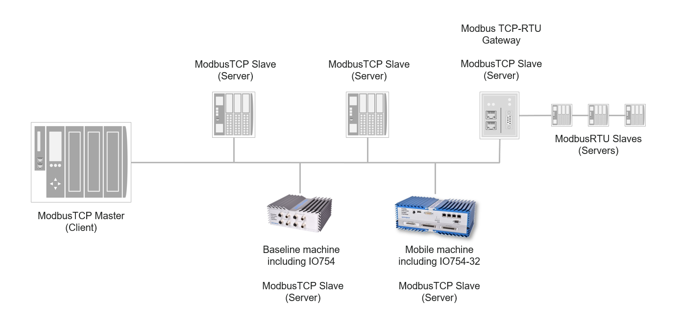
Application Example
Front Plate Description
IO754 PCI and PCIe modules
The IO754 acts as one Modbus TCP Server exclusively. The two RJ45 connectors
simply serve to build up a line-based network structure. Plug the cable from the
Modbus TCP Client or the previous Server into the first socket. Connect the
second socket with the next Modbus TCP Server. The LEDs described below indicate
the communication status of the single Modbus TCP Server.
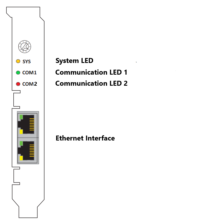
The rotary switch has no functional role.
IO754 mPCIe module
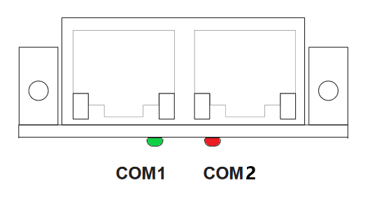
Note that in some real-time target machines,
the mPCIe module is reversed; that is, the Error LED appears on the right.
IO754-32 Multi-node simulator
The IO754-32 simulates 32 Modbus TCP Server nodes, split into two clusters
with 16 protocol chips each. Within a cluster, the nodes represent a line-based
network structure. Build up a combined network by connecting both center
sockets. You can use the leftmost or rightmost socket to connect the Modbus TCP
Client. Use the remaining socket to connect an external Modbus TCP Server or
another IO754-32 module.
Each node has two LEDs that indicate the communication status.

LED Status Description
Note that only the IO754 PCI and PCIe modules have the SYS LED. This LED does not
feature on the IO754 mPCIe module and the IO754-32 multi-node simulator.