IO752 Usage Notes
IO752 Usage Notes — Usage information about the
I/O module
Introduction
PROFINET is a master-slave communication protocol where the PROFINET controller
exchanges data with multiple PROFINET devices. To set up PROFINET communication, you
import the device description files (GSDML file) of all PROFINET devices into your
PROFINET controller configuration tool or PLC programming tool (Siemens STEP 7 or
TIA Portal, for example). The GSDML file is an xml file that includes the device
identity (vendor ID, device ID) and the information about available data modules.
Every PROFINET device comes with such a file.
The IO752 and IO752-32 can be used to simulate PROFINET devices from different
vendors. The simulation requires the import of the corresponding GSDML file. You
import the GSDML file in the IO752 Setup block mask which automatically sets the
device identity. In this block mask, you further set the device's station name which
serves as an address in the PROFINET network and which the PROFINET controller uses
to find a device. You finally assemble the input and output data images according to
the information retrieved from the GSDML file about modules, sub-modules and data
items.
During runtime, these data items are exchanged with the remote PROFINET controller
according to the timing set in the controller/network configuration. To get access
to the data items from the Simulink model, you use the IO752 Send and Receive
blocks. Use the Send block for the input data items which are sent to the
controller. Use the Receive block for the output data items which are received from
the controller. The input direction is from the field to the controller. The output
direction is from the controller to the field level.
Module Configuration
With PROFINET, a module is a logical unit that can have process data. In this
documentation the terms "data module" and "module" refer to such modules, whereas
the term "I/O module" refers to the I/O modules that you can install in Speedgoat
real-time target machines.
A PROFINET device consists of physical slots. Slots have sub-slots. You plug
modules into slots and sub-modules into sub-slots. Modules can have fixed
sub-modules, which are plugged into fixed sub-slots. Modules also support
usable
sub-modules that can be individually plugged into certain
sub-slots. Each device has a maximum number of slots and each slot has a maximum
number of sub-slots. Sub-modules have data items: the actual data that is cyclically
exchanged between the controller and the device. In addition, sub-modules can have
records. Records usually serve as parameters and can be acyclically read and written
by the PROFINET controller.
The very first module is the Device Access Point (DAP), which usually resides in
slot 0. The DAP determines the usable modules for the subsequent slots. DAPs rarely
have sub-modules with cyclic data but have fixed sub-modules with records that allow
the remote PROFINET controller to parametrize the device and its interfaces.
See this example of a generic module configuration:
All the available Device Access Points, modules, sub-modules and data items for a
PROFINET device are described in the device's GSDML file. The file limits the number
of possible slots and describes which module can be plugged into a certain slot.
The module configuration for the IO752 can be done in the IO752 Setup block mask.
After importing the GSDML file of the device to be simulated, a table control allows
the user to install available modules and sub-modules in slots and sub-slots
according to the rules in the GSDML file. All slots and sub-slots are virtual within
the IO752 device driver.
The configuration of a motor drive from Siemens with one control unit, one infeed
module and 2 servo motor modules looks like this:
The configuration of an ET200SP from Siemens with one 16-channel digital input
module, one 16-channel digital output module, one 4-channel analog input module and
one 2-channel analog output module looks like this:
Front Plate Description
IO752 PCI and PCIe modules
The IO752 acts as one PROFINET Device exclusively. The two RJ45 connectors
simply serve to build up a line-based network structure. Plug the cable from the
PROFINET Controller or the previous Device into the first socket. Connect the
second socket with the next PROFINET Device. The LEDs described below indicate
the communication status of the single PROFINET Device.
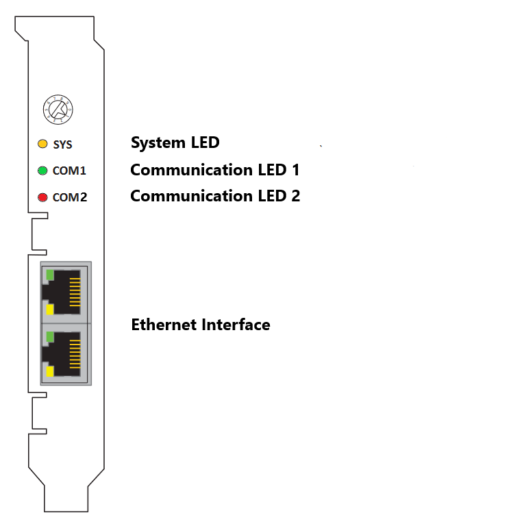
The rotary switch has no functional role.
IO752 mPCIe module
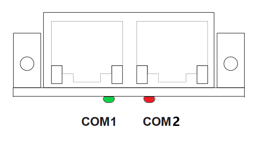
Note that in some real-time target machines,
the mPCIe module is reversed; that is, the Error LED appears on the right.
IO752-32 Multi-node simulator
The IO752-32 simulates 32 PROFINET Device nodes, split into two clusters with
16 protocol chips each. Within a cluster, the nodes represent a line-based
network structure. Build up a combined network by connecting both center
sockets. You can use the leftmost or rightmost socket to connect the PROFINET
Controller. Use the remaining socket to connect an external PROFINET Device or
another IO752-32 module.
Each node has two LEDs that indicate the communication status.

LED Status Description
Note that only the IO752 PCI and PCIe modules have the SYS LED. This LED does not
feature on the IO752 mPCIe module and the IO752-32 multi-node simulator.