- Module ID
The Module ID has two functions:
It logically connects the Setup block and its I/O blocks
It also informs the auto-search feature of the PCI Slot parameter. If only
one I/O module of this family is installed, the Module ID must be set to
1. To see how each I/O module maps to a
Module ID, use this Speedgoat API:
speedgoat.getIoInterfaces("TargetName", "mySpeedgoat")
This Setup block belongs to two families of I/O modules that use the same hardware
for multiple protocols. Across both families, the Module ID must be unique.
IO64X/IO75X (single-node modules): IO641,
IO642, IO643, IO644, IO750, IO751, IO752, IO753, IO754, IO755, IO756,
IO758
IO64X-32/IO75X-32 (multi-node modules):
IO642-32, IO752-32, IO754-32, IO756-32
If the PCI Slot parameter is set to -1
(auto-search), the Module ID must be in the range 1:n, where 'n' cannot be larger
than the number of modules of this type installed in the target machine. Not all
installed I/O modules need to be used.
To use this Setup block with a multi-node I/O module (IO75X-32 family), the Module
ID must be defined as a two-element vector. The second vector element is the
sub-module ID. It describes the specific node (1:32) within the I/O module. The 32
nodes are internally connected to form two linear networks (daisy-chain), where the
first and the last node of both chains are externally accessible. If one node is not
configured (has no Setup block), the chain terminates at this point. The sub-module
IDs must therefore start at node 1, 16, 17 or 32 and not have any gaps.
![[Note]](images/note.png) | Note |
|---|
When using I/O modules of both families simultaneously (single-node and
multi-node I/O modules), always use explicit addressing in the PCI Slot parameter. Ignore the Module IDs returned by
the getIoInterfaces function and instead assign unique Module IDs accross all
modules used. |
-
PCI Slot (-1: auto-search)
There are two approaches for mapping the block to a specific I/O
module installed in your target machine. All modules of the same
family (see Module ID above) must be configured using the same
method.
- Auto-Search: with the default value -1 the I/O module will be
automatically located in the target machine. If you have
multiple modules of the same family, the Module ID (first
vector element for a multi-node module) defines which module
is associated with this block. To see how each I/O module
maps to a Module ID, use this Speedgoat API:
speedgoat.getIoInterfaces("TargetName", "mySpeedgoat") - Explicit Addressing: to explicitly define the logical
address of the I/O module in the target machine, you can
provide the PCI bus and slot numbers as a vector: [bus,
slot]. To determine these numbers, run the following command
in the MATLAB command window:
speedgoat.getIoInterfaces("TargetName", "mySpeedgoat", "Advanced", true)Note
that the PCI address can change whenever an I/O module is
added or removed. Usually, auto-search is the best option.
- Name of Station
PROFINET uses a name-based station addressing method. The name must be
unique in the network and must match the name of the related device node
in the PROFINET controller configuration.
The following rules apply to the station name:
The station name must be a character array with a total length
between 1 and 240 characters
The station name consists of one or more labels separated by a
dot (.)
Each label must have a length between 1 and 63
characters
Labels may only contain lowercase letters (a–z), digits (0–9),
and hyphens (-)
Labels must not start with a hyphen (-)
Labels must not end with a hyphen (-)
Labels must not contain consecutive hyphens (--)
Empty labels are not allowed (e.g., leading dots, trailing
dots, or consecutive dots)
- Bus Start
This parameter specifies the time the I/O module should start the
communication on the network.
On model initialization: The I/O module starts the
communication immediately after the initialization of the
real-time application on the target. The communication is
maintained even if the real-time application stops
On model start: After the initialization of the real-time
application on the target (model download), the communication of
the I/O module with the network is off. The device starts the
communication when the real-time application starts. The device
stops the communication when the real-time application stops
- System Redundancy Support
This parameter activates PROFINET S2 System Redundancy support,
allowing the IO752 to connect to two redundant PLCs. In an S2 scenario,
the backup PLC takes over when the primary PLC fails (controller
redundancy).
The IO752 has one network access point (NAP) with two connectors,
allowing for the combination of controller and media redundancy. With
media redundancy, a ring topology turns into a line topology when the
connection breaks at one point. Support for media redundancy is
always active regardless of this checkbox
selection.
S2 System Redundancy requires a compatible IO752 hardware version with
redundancy-enabled firmware. If you select the checkbox for
standard hardware, the system log will show the
0xC0000123 error code, and the real-time application will not start.
Please ensure you have the necessary hardware and firmware before
enabling this option.
Network redundancy requires the PROFINET devices to support R1 and R2
System Redundancy. In general, the IO752 does not support R1 and R2 as
these modes require the device to feature two NAPs.
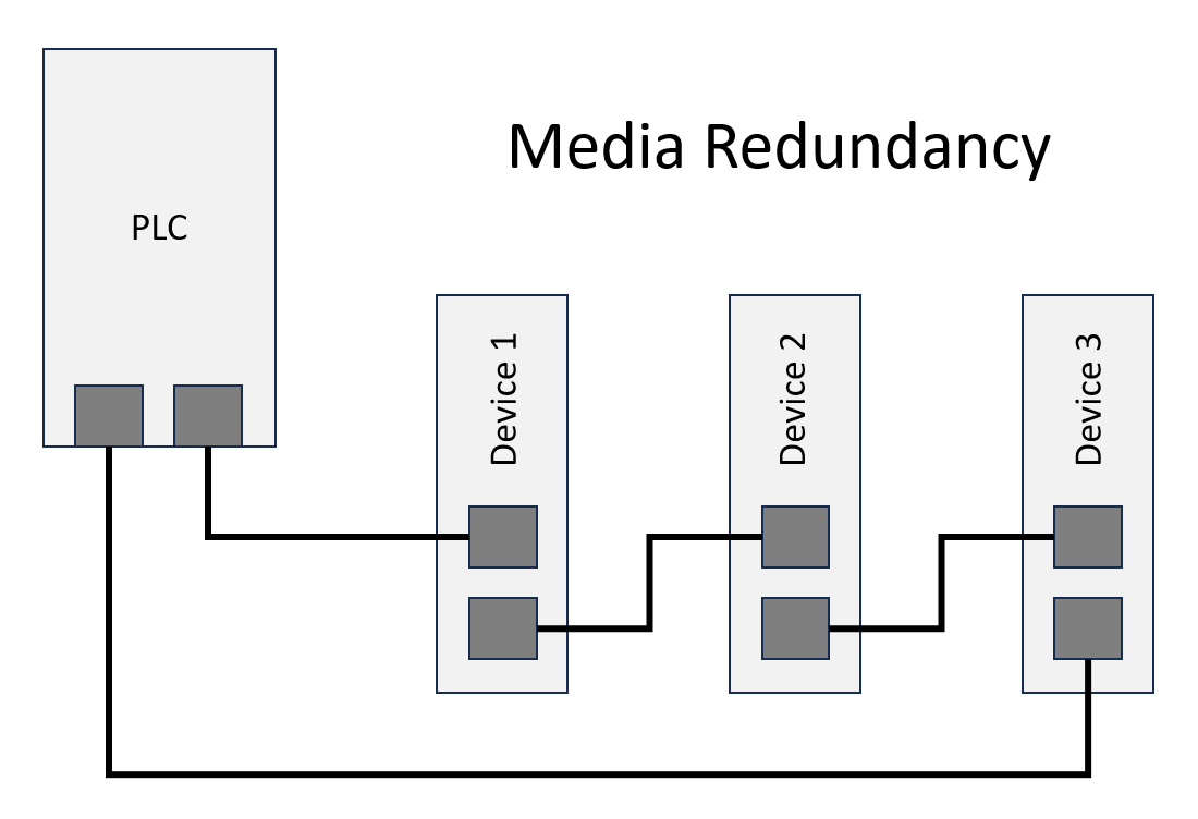
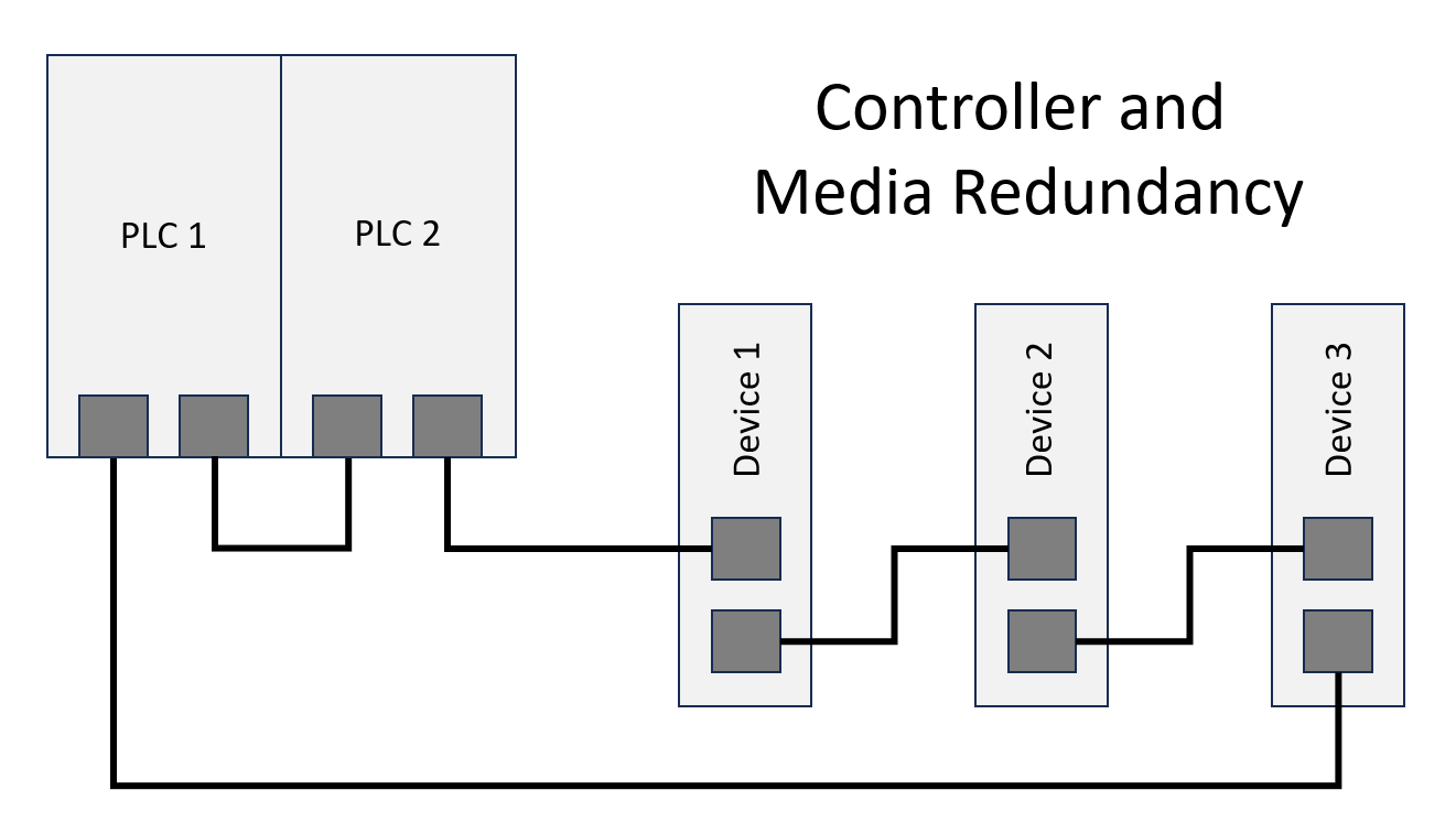
The IO752-32 does not support S2 System Redundancy. The checkbox,
therefore, serves no purpose when using this module.
- Record Access Always Succeeds
This parameter refers to the acyclic communication (RECORD access) and
defines how the I/O module reacts when record read and write messages
are received from remote PROFINET master devices.
If selected, the device always sends back confirmation messages
indicating read/write success even though the addressed record is not
defined. For read requests, the device sends an array of the requested
length where each element is 0.
If cleared, the device sends back confirmations that indicate failure.
Furthermore, a warning is added to the target system log for each failed
record access.
You define local records using the Record block.
- GSDML
Read the usage notes to learn about GSDML files.
- File Name
Enter the path to the GSDML file of the PROFINET device
that you want to simulate. Enter an absolute path to the
file or use a function to obtain a relative path. When done,
click the Import button to
import the data from the GSDML file.
Examples:
'C:\projects\profinet\GSDML-V2.34-Siemens-ET200SP-20190827.xml'
[pwd, '\..\GSDML-V2.31-ABB-FENA-20150120.xml']
Find the default GSDML file here:
[speedgoatroot, '\sg_blocks\cifx\eds\GSDML-V2.33-HILSCHER-CIFX RE PNS-20170919.xml']
This GSDML file contains multiple Device Access Points.
Always select CIFX RE/PNS V3.5.35 -
V3.x.
Type:
char
- Select
Opens a file dialog that lets you select a GSDML file in
the file system of your host computer. Afterwards, this
button writes the absolute path of the selected file to the
FileName parameter and
implicitly calls the Import
button.
- Import
Imports the device identity values from the specified
GSDML file and prepares the available data modules needed
for the Data Module
Configuration.