IO723 - Write Interface
IO723 - Write Interface — IO723 Write Interface
supporting database visualization and signal mapping
Library
Simulink® Real-Time™ - Speedgoat
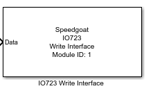
Description
The IO723 Write Interface block executes according to the settings in the IO723
Write Interface application. The execution primarily depends on the signal mapping
configured on the parsed database.
Each execution of an IO723 Write Interface block consists of one or more message
payloads being updated on the block's software buffer.
Each Write Interface block can be configured using the application, which can be
opened by double-clicking the block. The IO723 Write Interface application bridges
Simulink® model signals to RBS
project signals based on a manual mapping process. The RBS project must be configured using the FL3X
Config Software and the Setup block.
As an alternative to configuring the Write Interface block using the application,
the IO723 Block Config
class can be used to perform the mapping process programmatically.
The IO723 Write Interface block consists of a subsystem dynamically populated
with input ports, a dedicated IO723 byte packing block, IO723 Write blocks and the
interconnecting lines. Consequently, when an IO723 Interface Write block is placed
in a model, the link to the library is broken.
Ports
Inputs
-
Data
Data to be transmitted as a virtual bus structure. Datatypes for the
individual signals must comply with the payload size of the designated
PDU signal to which the individual signals will be mapped.
Parameters
-
Module ID
This ID defines the link to the corresponding Setup block
-
Sample Time
Defines the base sample time at which this driver block gets its sample hit. This
parameter can also be set to -1 for inherited
sample time. The units are in seconds.
Configure Interface
When configuring the interface, there is one tab for each communication protocol.
In the RBS project, all available networks
corresponding to one protocol are combined into one tab. Each tab can be configured
differently from the others. The configuration settings of each tab are combined
into one when applying the final configuration settings.
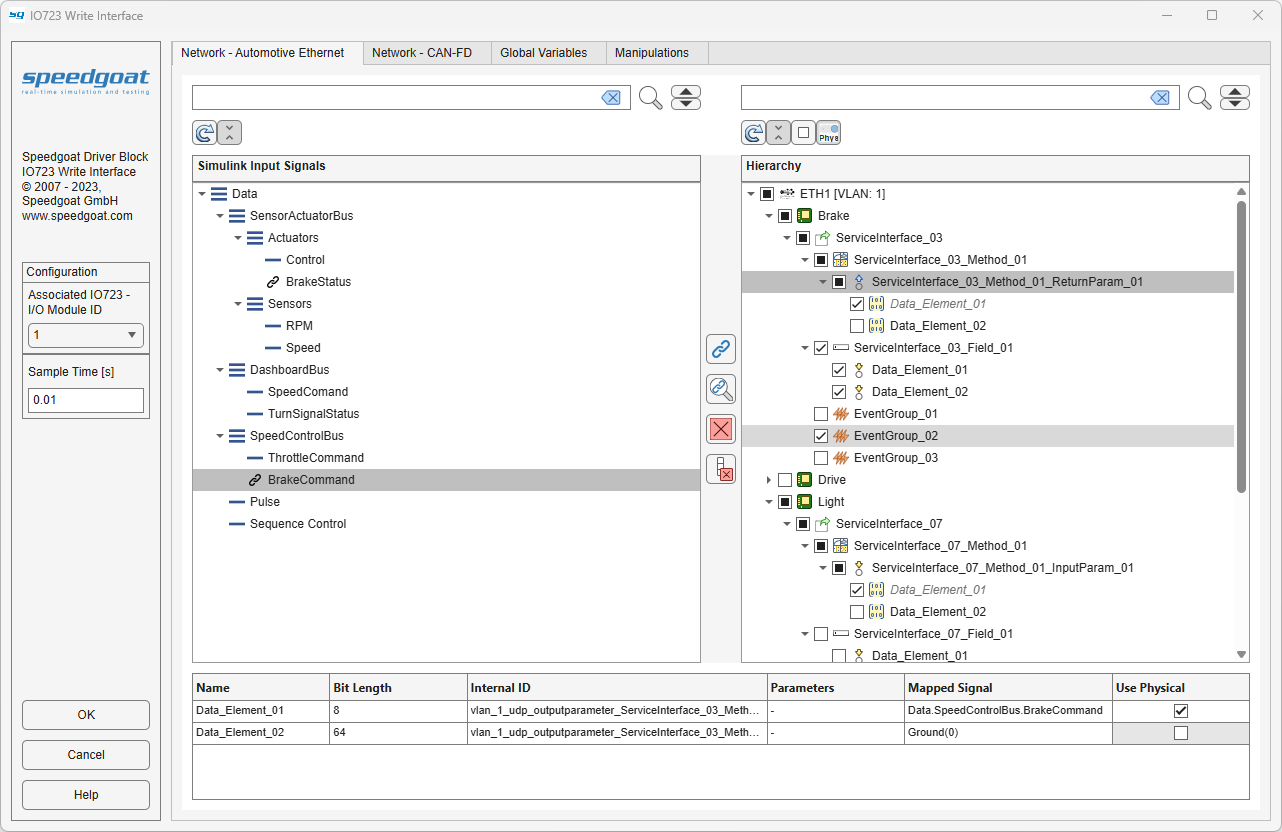
Simulink Input Signals
The Simulink Input Signals shows a
tree view of the structure of the input Simulink bus signal. The icons
indicate if a node is a bus (located at the top of a branch) or a signal
(located at the bottom of a branch). The icon changes to a link symbol
if a signal is currently mapped.
Hierarchy
The Hierarchy shows a tree view of
the RBS project structure. The icons
indicate the node type in the corresponding protocol structure. Nodes at
any level can be enabled using the adjacent checkboxes. Enabling or
disabling a node higher in the hierarchy will also automatically change
the status of all subordinate nodes.
Details Table
The Details table shows all the
information available to the subordinate nodes of the node currently
selected in the Hierarchy tree. No
actions are available for this table.
Search and Options Panel
-
Search
The Simulink Input Signals and the
Hierarchy tree each have their own
Search field available. Any nodes
found will be highlighted in the respective tree. You can cycle through
highlighted nodes using the up and down arrow buttons next to the
respective search button. Clear the search field to clear the node
highlighting.
-
Refresh
The Refresh button will update both
the trees. Refreshing the Simulink Input
Signals tree will update the structure of the input
Simulink bus signal of the Simulink model. Refreshing the Hierarchy tree will update the structure of
the RBS project configured in the
connected IO723 Setup block.
-
Expand All Nodes
The Expand All Nodes state button
will expand or collapse all nodes in the respective tree depending on
the state of the button.
-
Check All Nodes
The Check All Nodes state button will
check or uncheck all nodes in the Hierarchy tree depending on the state of the
button.
-
Check Selected Use Physical
The Check Selected Use Physical state
button will check or uncheck all Use
Physical properties of selected nodes in the Hierarchy tree depending on the state of the
button. Nodes with Use Physical enabled
will process mapped Simulink Input
Signals as physical values and if disabled process them
as a raw byte array. The physical attributes for processing a signal
with Use Physical enabled are defined
in the RBS project.
Mapping Panel
-
Map Signals
The Map Signals button links signals
from the two trees. To do this, one signal must be selected in the
Simulink Input Signals tree, and
one in the Hierarchy tree. Only one
signal from each tree can be selected. Only signals can be mapped and
they are always located at the bottom of a branch.
-
Highlight Mapped Signals
The Highlight Mapped Signals button
shows all signals in the Hierarchy tree
that have been mapped to a specific Simulink Input
Signals signal. You can cycle through the nodes found
using the up and down buttons next to the search field of the Hierarchy tree.
-
Clear Selected Mapping
The Clear Selected Mapping button
resets all the highlighted signals in the Hierarchy tree to the default 'Ground(0)'.
-
Clear Entire Mapping
The Clear Entire Mapping button
resets all the signals in the Hierarchy
tree to the default 'Ground(0)'.
Configure Global Variables
When configuring the interface, use the tab for configuring values for global
variables. In the RBS project, all available global
variables are combined into one tab.
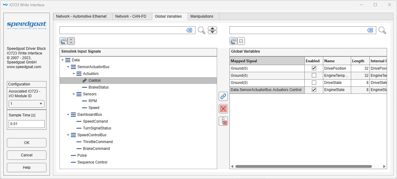
Simulink Input Signals
The Simulink Input Signals shows a
tree view of the structure of the input Simulink bus signal. The icons
indicate if a node is a bus (located at the top of a branch) or a signal
(located at the bottom of a branch). The icon changes to a link symbol
if a signal is currently mapped.
Global Variables
The Global Variables shows a table
view of the global variables defined in the RBS
project structure. Access to altering the value of a
global variable using a signal can be enabled using the adjacent
checkbox.
Search and Options Panel
-
Search
The Simulink Input Signals tree and
the Global Variables table each have
their own Search field available. Any
nodes or rows found will be highlighted in the respective tree or table.
You can cycle through highlighted Simulink Input
Signals nodes using the up and down arrow buttons next to
the respective search button. Clear the search field to clear the node
or row highlighting. Nodes and rows are searched based on their node
name or Name only.
-
Refresh
The Refresh button will update both
the tree or table. Refreshing the Simulink Input
Signals tree will update the structure of the input
Simulink bus signal of the Simulink model. Refreshing the Global Variables table will update the
structure of the RBS project configured
in the connected IO723 Setup block.
-
Expand All Nodes
The Expand All Nodes state button
will expand or collapse all nodes in the Simulink
Input Signals tree depending on the state of the
button.
-
Check All Variables
The Check All Variables state button
will check or uncheck all variables in the Global
Variables table depending on the state of the
button.
Mapping Panel
-
Map Signals
The Map Signals button links signals
from the tree to the table. To do this, one signal must be selected in
the Simulink Input Signals tree, and
one variable in the Global Variables
table. Only one signal from the Simulink Input
Signals tree can be selected. Multiple variables can be
selected in the Global Variables table,
also by highlighting them using the search function.
-
Clear Selected Mapping
The Clear Selected Mapping button
resets all the highlighted or selected variables in the Global Variables table to the default
'Ground(0)'.
-
Clear Entire Mapping
The Clear Entire Mapping button
resets all the variables in the Global
Variables table to the default 'Ground(0)'.
Configure Manipulations
When configuring the interface, there is a tab for enabling and configuring values
of manipulations during runtime. In the RBS
project, all available manipulations and sequences are combined into one
tab. Manipulations can be configured only once for each associated IO723 - I/O
Module ID. If two IO723 Write Interface applications are configured for the same
Module ID, only the one opened first has a manipulations tab.
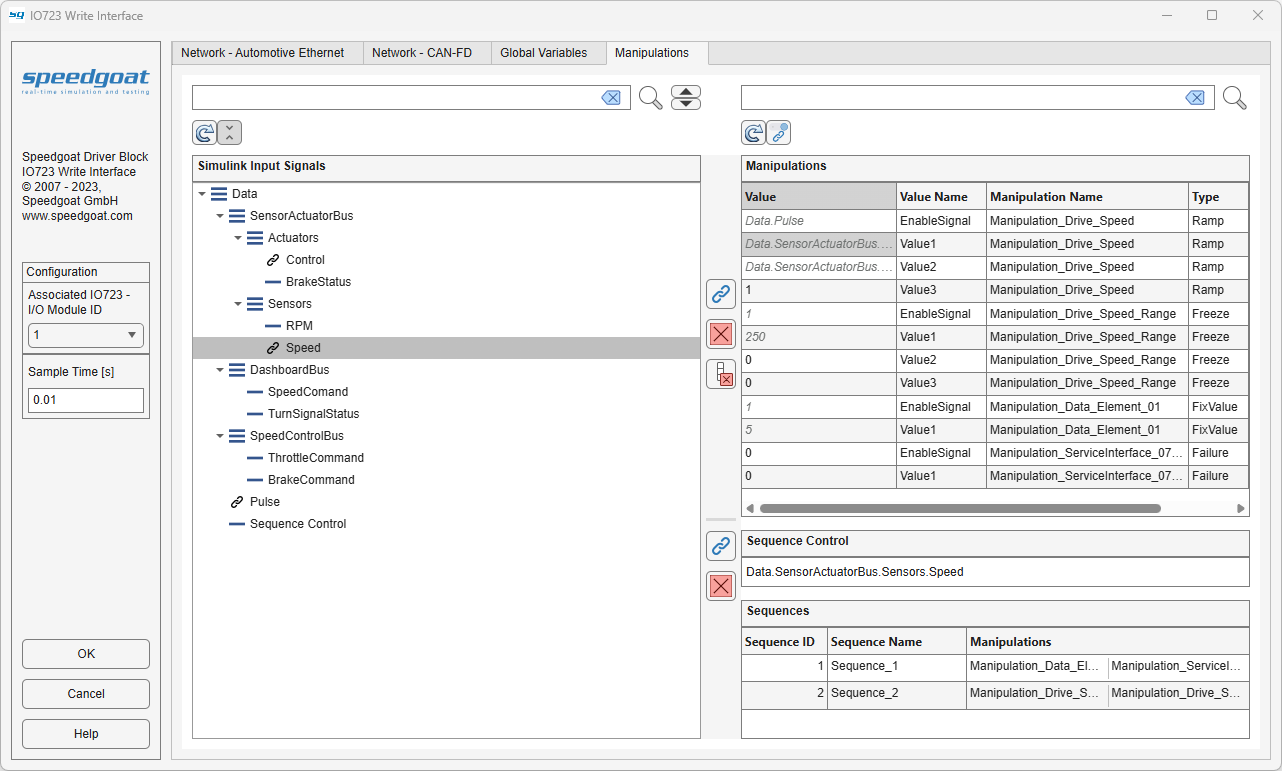
Simulink Input Signals
The Simulink Input Signals shows a
tree view of the structure of the input Simulink bus signal. The icons
indicate if a node is a bus (located at the top of a branch) or a signal
(located at the bottom of a branch). The icon changes to a link symbol
if a signal is currently mapped.
Manipulations
The Manipulations shows a table view
of the manipulations defined in the RBS
project structure. The individual manipulations can be
enabled or disabled by setting the Value of Value Name
'EnableSignal' to '1' or '0' respectively. Alternatively the
'EnableSignal' can be mapped to a Simulink Input
Signal from the tree view. Also Value from rows with Value
Name 'ValueX' can be set to any uint32 scalar, rather
than the default one defined in the RBS
project, or mapped to a Simulink
Input Signal.
Search and Options Panel
-
Search
The Simulink Input Signals tree and
the Manipulations table each have their
own Search field available. Any nodes
or rows found will be highlighted in the respective tree or table. You
can cycle through highlighted Simulink Input
Signals nodes using the up and down arrow buttons next to
the respective search button. Clear the search field to clear the node
or row highlighting. Nodes and rows are searched based on their node
name or Manipulation Name only.
-
Refresh
The Refresh button will update both
the tree or table. Refreshing the Simulink Input
Signals tree will update the structure of the input
Simulink bus signal of the Simulink model. Refreshing the Manipulations table will update the structure
of the RBS project configured in the
connected IO723 Setup block.
-
Expand All Nodes
The Expand All Nodes state button
will expand or collapse all nodes in the Simulink
Input Signals tree depending on the state of the
button.
-
Enable Value Mapping
The Enable Value Mapping state button
controls whether Value can be edited or
mapped in the Manipulations table. When
the button is disabled, the default Value from the RBS
project are used. In this state, only rows with Value Name 'EnableSignal' are
available.
Manipulations Mapping Panel
-
Map Signals
The Map Signals button links signals
from the tree to the table. To do this, one signal must be selected in
the Simulink Input Signals tree, and
one row in the Manipulations table.
Only one signal from the Simulink Input
Signals tree can be selected. Multiple rows can be
selected in the Manipulations table,
also by highlighting them using the search function.
-
Clear Selected Mapping
The Clear Selected Mapping button
resets all the highlighted or selected rows in the Manipulations table to their default Value from the RBS
project or to '0'.
-
Clear Entire Mapping
The Clear Entire Mapping button
resets all the rows in the Manipulations table to their default Value from the RBS
project or to '0'.
Sequence Control Mapping Panel
-
Map Sequence Control
The Map Sequence Control button links
a signal from the tree to the Sequence
Control. To do this, exactly one signal must be selected
in the Simulink Input Signals
tree.
The value of the signal mapped to Sequence
Control, controls which sequence is active if any.
Sequences are activated by matching their Sequence
ID. To use the individual manipulations instead of any of
the sequences, the Sequence Control
value can be set to '0'. The value of Sequence
Control may also be edited to any value inside the uint32
range instead of mapping it.
-
Clear Sequence Control Mapping
The Clear Sequence Control Mapping
button resets the Sequence Control to
'0'.