IO643 Usage Notes
IO643 Usage Notes — Usage information about the
I/O module
Description
This section describes how to configure the CANopen network.
I/O Module configuration with SYCON.net
During initialization of the real-time application, the IO643 Setup block reads a
configuration file from the hard drive of the target machine and configures the
CANopen Master protocol stack. Use the SYCON.net configuration tool to create such a
file.
![[Tip]](images/tip.png) | Tip |
|---|
Download the SYCON.net configuration tool from the Speedgoat Customer Portal. Login to
your Speedgoat account. In the Downloads section, navigate to Software and click
SYCON.net (v1.500 Build 231214). |
In addition to this short introduction, please read the SYCON.net help
documentation for detailed information about how to set up a CANopen network and
export the module configuration file.
Open SYCON.net and create a new project
In the right window, select the Fieldbus
tab, navigate to CANopen > Master, select the CIFX
CO/COM item and drag it to the bus line in the Network View window
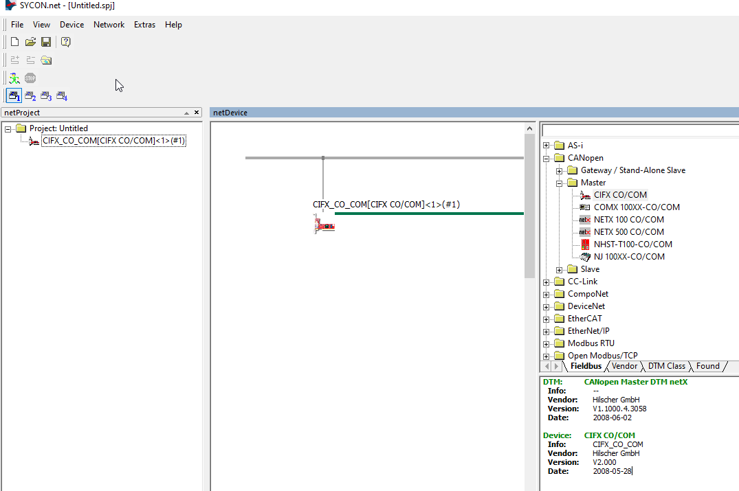
Double-click the master node in the Network
View window, navigate to Bus
Parameters and set the desired Node
ID and Baud rate
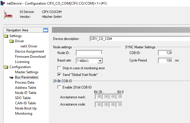
In the main menu bar, navigate to Network
and click Import Device Descriptions.
Select the device description files (*.eds) of the slaves included in your
CANopen network
In the right window, select the Fieldbus
tab, navigate to CANopen > Slave, select the slave device and drag it to the
master bus line in the Network View
window
Double-click the slave nodes in the Network
View window and configure the PDO
mapping according to the corresponding device description
file of the slave
Double-click the master node in the Network
View window, navigate to Node ID
Table and set the appropriate Node ID for each slave
Save the project
Right-click the master node in the Network
View window, navigate to Additional
Functions > Export and click
DBM/nxd. Save the file to a destination
of your choice
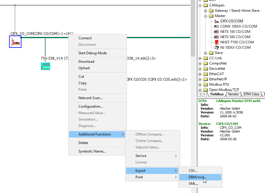
Configuration of the Send and Receive Blocks
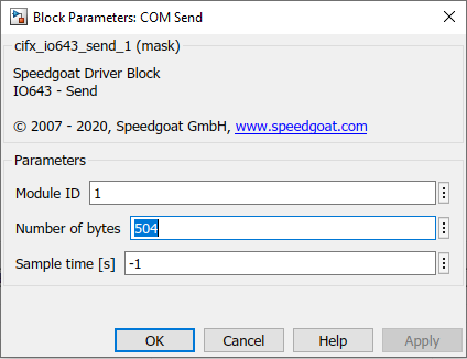
To access the data sent and received by the I/O module, add one Send and one
Receive block to your Simulink model. The Number of
Bytes block parameters result from the PDO configuration in the
SYCON.net project.
In the SYCON.net project, double-click the master node and navigate to the
Address Table. There you can find the
length and the offset of each PDO in the RX and TX data areas of the I/O
module
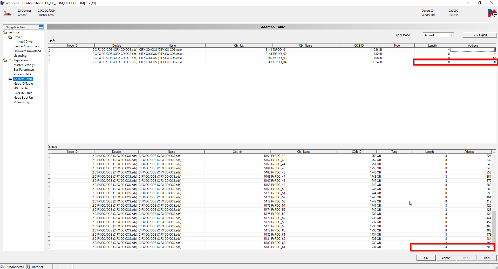
The upper table is labeled Inputs and
contains the TX PDOs of the slaves. This is
the data the master receives from the slaves. Add the Length of the last row to the Address of the last row and enter the result into the
Number of Bytes parameter of the
Receive block in Simulink

The lower table is labeled Outputs and
contains the RX PDOs of the slaves. This is
the data the master sends to the slaves. Add the Length of the last row to the Address of the last row and enter the result into the
Number of Bytes parameter of the
Send block in Simulink
| Tip |
|---|
You can autogenerate the entire data assembly and extraction part for your
model including Send, Receive, Packing and Unpacking blocks with the help of the
createFromSycon function. |
PDO communication with non-conformant CANopen slave devices
By default, the IO643 sends an SDO request to all configured slaves to read object
0x1000, which contains device type information. The module reads this object not
only to check the device type but also to check if SDO communication is supported.
Slave devices that do not support SDO or do not have an object dictionary will not
respond to this read request. In such cases, the IO643 will not start sending PDOs
to the slaves or process received PDOs.
To prevent the IO643 from sending this specific SDO read request, all SDO-relevant
configuration options must be disabled in the SYCON.net project. This informs the
module that no SDO communication is required during runtime and that reading object
0x1000 is not required. The module will then just start sending the configured
PDOs.
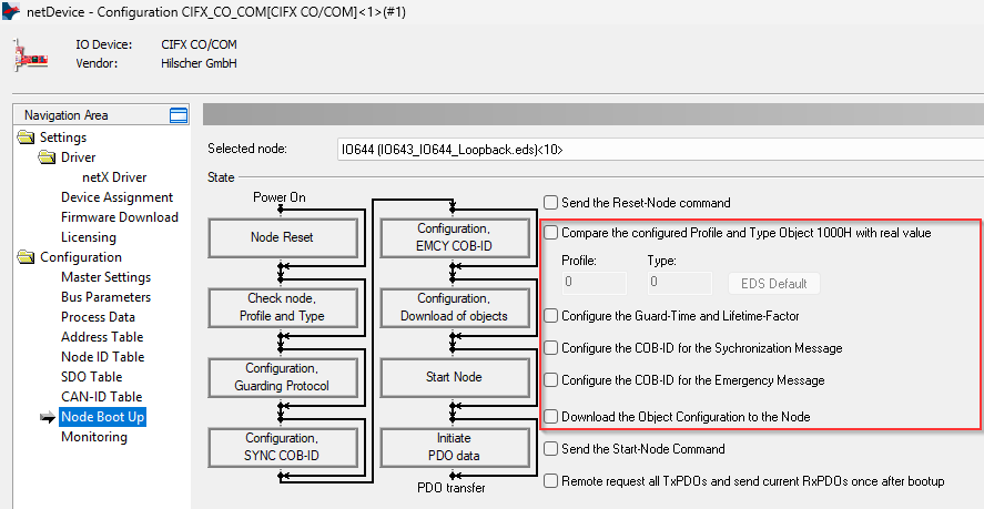
In the SYCON.net project, double-click the master node and navigate to the
Node Boot Up. Clear the checkboxes as shown in
the following screenshot:
Front Plate Description
IO643 PCI and PCIe modules
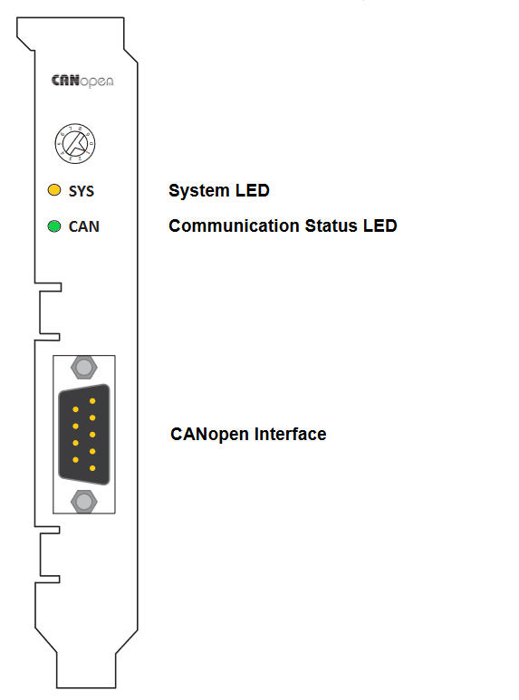
The rotary switch has no functional role.
IO643 mPCIe module
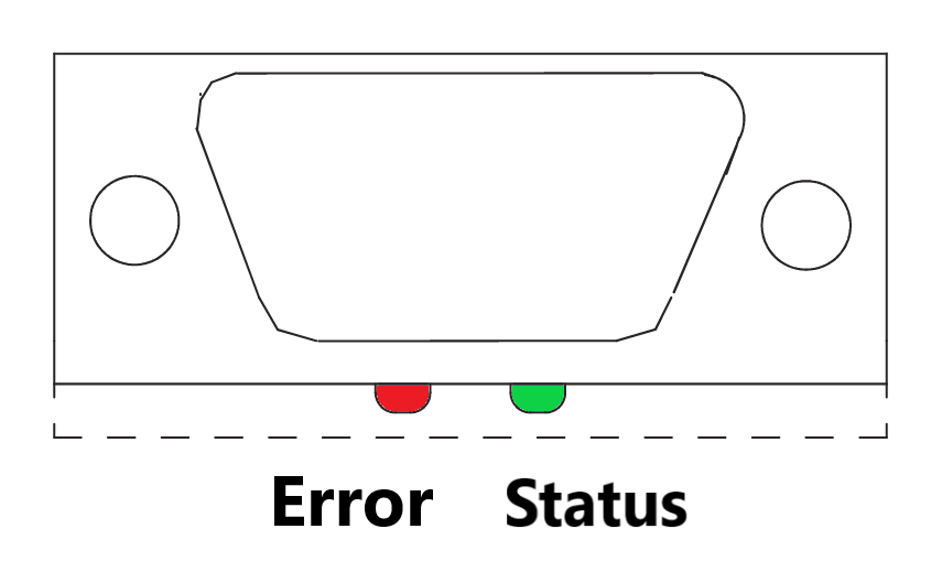
Note that in some real-time target machines,
the mPCIe module is reversed; that is, the Error LED appears on the right.