IO643/IO644 Pin Mapping
IO643/IO644 Pin Mapping — Reference information about
the I/O module connector
I/O Pin Mapping for CANopen
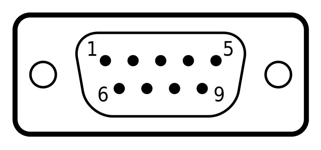
The 9-pin Male D-Sub connector provides one isolated CANopen interface according
to ISO 11898.
Wiring
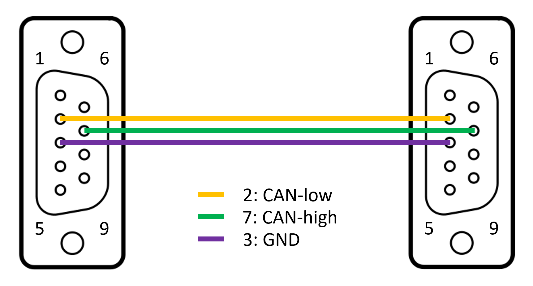
Use a standard CAN cable with female sockets to connect the I/O module with
external CANopen devices. CANopen devices are connected in a line topology with each
other (from A to B, B to C, and so on). As almost every CANopen device has only one
connector, use Y split cables to connect multiple devices to the network.
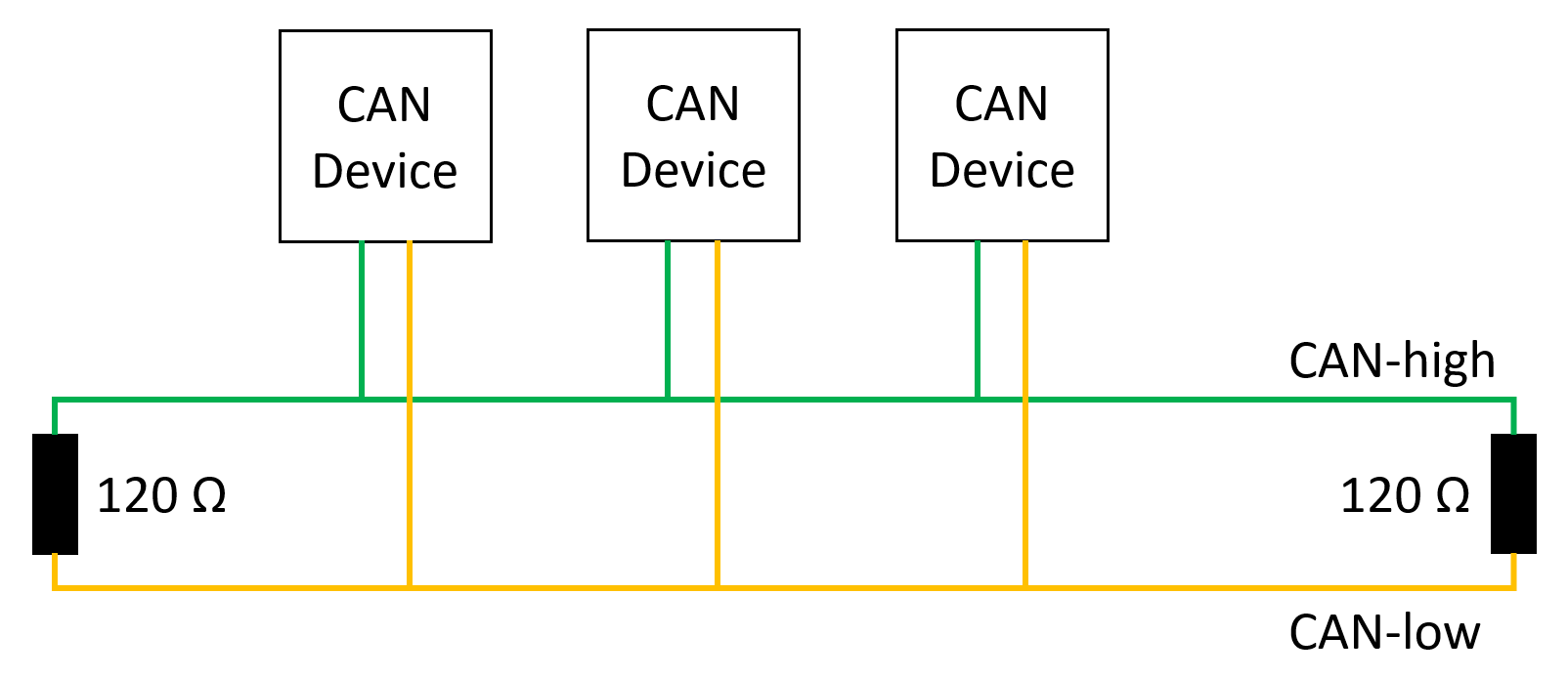
For proper operation, a CANopen topology requires 120 ohm terminating resistors
on both ends. The IO643 and IO644 I/O modules do not include termination resistors.
Instead, Speedgoat provides standard termination adapters which can be inserted
between the I/O module and the CAN cable. Termination resistors are not mandatory
for very short distances.