IO614 - Setup
IO614 - Setup — This block allows the IO614 module
to be configured
Library
Simulink Real-Time - Speedgoat
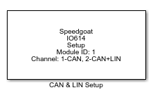
Description
For each IO614 module in your target machine there should be exactly one "CAN
& LIN Setup" driver block in your model. This block allows all the supported I/O
types of this module to be configured and therefore impacts on all the other driver
blocks.
Ports
This driver block has no input or output ports.
Parameters
Module setup
-
Module ID
The Module ID must be unique among all IO611 Setup blocks in your
model. It has two functions:
It defines the logical connection to associate the Setup,
Read and Write blocks with each other.
It is relevant for the PCI slot auto-search feature: If
only one IO614 is installed, the Module ID must be set to 1.
If n modules are installed, it must be in the range 1:n. Not
all the modules installed in the target machine need be
used.
-
Drive letter on target machine
Choose on which drive this driver block should look for the firmware
to load on the module, once the model is downloaded to the machine. The
default setting for this parameter is 'C:', as the firmware will be
located on the C drive by default.
-
PCI slot (-1:autosearch)
There are two approaches for mapping the blocks to a specific IO614
module installed in the target machine. All IO614 modules must be
configured using the same method.
Auto-Search: The default value '-1'
lets the real-time target machine auto-search for the I/O
module. The priority is defined by the Module ID. The module
with the lowest PCI bus/slot number is associated with
Module ID 1, the next module found is associated to Module
ID 2, and so on. Please refer to your target machine manual
for the specific slot sequence.
Explicit Addressing: The location of
the module inside the target machine can be explicitly
defined using the format '[BusNumber, SlotNumber]'. To
determine these numbers, type
speedgoat.showInstalledIoModules in the MATLAB command
window.
-
Channel Selection
In this group box, you can specify the configuration for each channel.
Note that LIN is only available on channel 2.
CAN
This tab is only visible if at least one CAN channel is enabled. There will be
one group box per enabled CAN channel, labeled with the number of the channel.
There is also one additional group box called Init./Term. Structures, where you
can define CAN messages sent during initialization and termination of the CAN
write driver blocks.
-
Operation Mode:
Choose High-Speed or Low-Speed operation. Low-Speed operation is
according to ISO 11898-3. High-Speed operation is according to ISO
11898-2. Note that the Operation Mode is only configurable for channel
1, as the other CAN channels only support High-Speed operation.
-
Baud rate
The baud rate for this CAN channel. This control allows the most
commonly used values to be selected. If special bit timing is needed,
then select the User defined here and use the "User defined baud rate"
parameter below.
-
User defined baud rate
If the defined User has been selected in the "Baud rate" parameter
above, this parameter is used to configure the bit timing. The parameter
is a vector with the following elements:
For an explanation and calculation of the bit-timing
values, check the free individual bit-timing table on can-wiki,info using the following parameters:
Note that the Bitrate indicated on this website is in
thousands (e.g. Bitrate = 1000 accords to 1Mbaud).
-
Standard Acceptance Mask
The rule to decide whether a CAN message with a standard ID (11 bits)
is accepted on this channel. The message is accepted if the following
rule is true:
Set the StdMask element to zero (the default) to disable
the rule. Note that this parameter takes a decimal value. See the "Usage
notes" section for examples of how to set this parameter.
-
Extended Acceptance Mask
The rule to decide whether a CAN message with an extended ID (29 bits)
is accepted on this channel. The message is accepted if either of the
following rules is true:
Set the ExtMask element to zero (the default) to disable
the rule. Note that this parameter takes a decimal value. See the "Usage
notes" section for examples of how to set this parameter.
-
Initialization Structures
Defines CAN messages sent during initialization of the Setup block.
For more information, see: Initialization and
Termination CAN Messages.
-
Termination Structures
Defines CAN messages sent during termination of the Setup block. For
more information, see: Initialization and
Termination CAN Messages.
LIN
This tab is only visible if LIN on channel 2 is enabled.
-
Operation Mode
The IO614 can be configured to act as a master or a slave. In the LIN
topology, only one master is allowed per network.
-
Baud rate
This parameter is valid for master and slave operation. Range between
1000 and 20000.