IO614 - CAN Status
IO614 - CAN Status — This block provides CAN bus and
controller status information
Library
Simulink Real-Time - Speedgoat
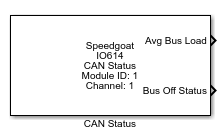
Description
This block provides CAN bus and controller status information.
Ports
Outputs
-
All
Status information of the CAN channel and the controller. The
individual signals can be enabled or disabled in the driver mask. See
the "Parameters" section.
Inputs
-
Bus Reco
With "1" impulse, the Status block will attempt to recover from a BUS
OFF state. After bus restart, the value should be set to zero.
Data
Types:uint32
Parameters
Setup
-
Module ID
Specifies the ID of the IO61X module to which this driver block should
be connected. It must correspond to the module ID of the according setup
block. Check the setup block help for more details.
-
Sample Time
Defines the base sample time at which this driver block gets its
sample hit. It can also be set to -1 for inherited sample time. The
units are in seconds.
-
Get Status for Channel
Choose the CAN-FD channel to which this driver block should give
status information.
-
Status Selection
Choose which types of status information to access with this driver
block. The selectable status outputs for this block in the Status-Tab
will change accordingly.
Port: Status information about the CAN channel to which this
driver block is mapped. The term Port is used for Channel with
this parameter in order to maintain backwards
compatibility.
Controller: Configuration information about the CAN controller
of the channel to which this driver block is mapped.
All: Both of the above.
-
Bus OFF
Defines if and when the CAN controller will try to recover from a "BUS
OFF" status.
Off: The bus will stay OFF, no recovery is
attempted.
Auto: The Status block will restart the CAN stack for all
channels to recover from the BUS OFF state.
Manual: The "Bus Reco" Input is added. Set to "1" for a
Manual bus restart.
Status
Here, the user can select the required status signals. The selected signals
appear as block outputs.
-
Average Bus Load (0 – 100%)
Average bus load in percent. The CAN controller computes the bus load
every 4096 bits. In most cases it is sufficient to request the bus load
once per second. For example, for 500 kBaud: 500kBaud = 500bit/ms =>
2µs/bit * 4096bit = 8.2ms update time for the bus load.
-
Operating Mode
-
Prescaler (BPS)
This value corresponds to the BPS value of the selected baud rate in
the corresponding setup block.
-
Time Segment 1 (TSEG1)
This value corresponds to the TSEG1 value of the selected baud rate in
the corresponding setup block.
-
Time Segment 2 (TSEG2)
This value corresponds to the TSEG2 value of the selected baud rate in
the corresponding setup block.
-
Synchronization Jump Width (SJW)
This value corresponds to the SJW value of the selected baud rate in
the corresponding setup block.
-
Transmission Pending
The CAN controller is sending a message.
-
Data Overrun Occurred
This flag will be set if the receive queue is full and the CAN
controller cannot write the next received message to the queue. To reset
the flag, the controller must be stopped and started again.
-
Error Warning Limit Exceeded
Each CAN controller has an internal error counter which counts
physical bus problems.
-
Bus Off Status
Uses the same internal error counter as the warning output above:
-
Init Mode Active
-
Bus Coupling Error
Indicates a bus coupling error if CAN LS is used.
-
Bus Recovery Counter
This uint32 counter is incremented each time the bus-recovery process
of the CAN channel is finished.