IO421 - Synchro/Resolver Read
IO421 - Synchro/Resolver Read —
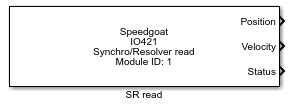
Reads the IO421 Synchro/Resolver inputs
Library
Simulink Real-Time - Speedgoat
Description
The IO421-2 sub-module measures up to four Synchro or Resolver. Each channel has
separate inputs for the reference (excitation) and the S signals.
The characteristics of the sub-module depend on the factory configuration selected
at the time of the order. This information is available in a separate documentation
shipped with the device.
Ports
Inputs
-
Max RPS
The maximum rotational velocity. Units are RPS (revolutions per
second). This port is enabled or disabled in the 'Input and output ports
configuration' tab of this block's dialog box.
Outputs
-
Position
The measured rotational position in radians. This port is enabled or
disabled in the 'Input and output ports configuration' tab of this
block's dialog box.
-
Velocity
The measured rotational velocity in revolutions per second RPS. This
port is enabled or disabled in the 'Input and output ports
configuration' tab of this block's dialog box.
-
Status
A bit field indicating test, signal, and reference statuses.
Bit0: the status of the BIT (built-in tests
procedure).
Bit1: the signal status. If the signal is below 90% of
the expected threshold, this flag is high.
Bit2: the reference status. If the reference is below
90% of the expected threshold this flag is high.
This port is enabled or disabled in the 'Input and
output ports configuration' tab of this block's dialog box.
All ports are vectors. The width of the vector, and the order of the corresponding
channels, is dependent on the configuration of the 'Channel vector'
parameter.
Parameters
Tab: Module Setup
-
Module ID
A unique module ID must be used for each type of IO421 module block in
your model.
The module ID has two functions:
It defines the logical connection to link the I/O module
driver blocks with each other
It also has an impact on the PCI slot auto-search feature: if
only one I/O module is installed, the module ID must be set to
1. If multiple modules are
installed, it must be in the range 1:n. Not all the I/O modules
installed in the target machine need to be used
-
Slot
The carrier board can contain up to three sub-modules. This parameter
indicates where is your IO421-1 located.
-
Active Channels
Select the active input/output channels in a vector. A defined number of channels
can be selected using square brackets, for example [1 2 3]. A sequence of channels
can be selected using a colon, for example, 1:4.
-
Sample Time
Defines the base sample time at which this driver block gets its sample hit. This
parameter can also be set to -1 for inherited
sample time. The units are in seconds.
-
PCI Slot (-1: auto-search)
There are two approaches for mapping this block to a specific I/O module installed
in your target machine. All modules of the same type must be configured using the
same method.
Auto-Search: with the default value -1 the I/O module will be automatically located in the
target machine. If you have multiple modules of the same kind, the
Module ID defines which module is associated with this block. To see how
each I/O module maps to a Module ID, use this Speedgoat API:
speedgoat.getIoInterfaces("TargetName", "mySpeedgoat")
Explicit Addressing: to explicitly define the logical address of the
I/O module in the target machine, you can provide the PCI bus and slot
numbers as a vector: [bus, slot]. To determine these numbers, run the
following command in the MATLAB command window:
speedgoat.getIoInterfaces("TargetName", "mySpeedgoat", "Advanced", true)Note
that the PCI address can change whenever an I/O module is added or
removed – usually, auto-search is the best option.
Tab: Synchro/Resolver
For all parameters in the table below you can either use a scalar value, which
applies to all channels, or a vector which is mapped to the Channels
vector.
-
Expected Signal Voltage VLL
This value is used in the internal signal detection circuit: When the
measured signal input falls below 90% of this value, the signal
status bit in the optional status output goes to its failure state.
-
Expected Reference Voltage VREF
This value is used in the internal signal detection circuit: When the
measured reference (excitation) input falls below 90% of this value,
the reference status bit in the optional status output goes to its
failure state.
-
Bandwidth Vector
Enter the bandwidth for each channel which can individually be
programmed between 6 [Hz] and 1280[Hz] (even numbers only). By selecting
a value of 0 the sub-module automatically sets the bandwidth.
-
Ratio Vector (1-256)
Enter the desired ratio as an integer number corresponding to the pair
of channels (CH 1&2 or CH 3&4) to be used for a two-speed or
multiple-speed configuration. Example: Gear ratio 36:1 = integer 36.
Values which can selected are 1-256, where 1 is for single speed. See
Synchro/Resolver connection methods for an example.
-
High Resolution Vector
The resolution can be individually selected by channel. Select either
'0' for 16-bit or '1' for 24-bit. Use 24-bit for two-speed configuration
otherwise 16-bit.
-
Synchro Vector
The S/D measurement format can be individually selected for each
channel. Enter a scalar or a vector having the same length as the
Channels vector. Possible values are '0' for Resolver or '1' for
Synchro.
-
Max RPS Vector
Enter the maximum measurable velocity (in revolutions per second) for
each channel. This value sets the velocity scale for each channel. This
value must be a scalar or a vector that is the same length as the
Channels vector value.
-
Latch all Channels before Reading Position Data
Select this check box to guarantee that all channels are latched
before being read. This ensures that all channels are sampled at the
same time. Note that selecting this option incurs a small additional
resource overhead.
Tab: Input and Output Ports Configuration
-
Show Position Output
When this parameter is checked, an output port labeled "Position" is
available. Its width is equal to channel count and the vector elements
are ordered as they are defined by the channel vector. This output
contains the linear position measured by the S/R module.
-
Show Velocity Output
When this parameter is checked, an output port labeled "Velocity" is
available. Its width is equal to channel count and the vector elements
are ordered as they are defined by the channel vector. This output
contains the velocity measured by the S/R module.
-
Show Status Output
When this parameter is checked, an output port labeled "Status" is
available. Its width is equal to channel count and the vector elements
are ordered as they are defined by the channel vector. The status value
is encoded in a 3-bit integer returned as a double and includes the
following channel information:
test status, weight of 0
signal status, weight of 1
reference status, weight of 2
Each status value is a binary value (0 = OK, 1 =
FAILURE). The driver encodes these binary values into a single signal.
For example, a status value of 6 (110) indicates that the test status is
OK and both signal status and reference status are FAILURE. If the board
does not provide a reference/excitation, the test status and reference
status have no meaning.
-
Show Input Port for Dynamic Max RPS
Select this check box to display an input port for all channels to be
used for specifying the maximum RPS dynamically. When you select this
check box, the input port signals are internally limited to between
11.9209 and 190.7348 RPS.