IO191 Usage Notes
IO191 Usage Notes — Usage information about the
I/O module
ADC Sample Rate
The IO191 I/O module can be configured to use up to eight single-ended or four
pairs of channels (differential mode) and can operate up to 250,000 samples per
second (SPS). The sample rate depends on the number of Active Channels (the sample
rate is aggregate) and the sampling mode (non-DMA or DMA).
For non-DMA, the IO191 is configured for manual sampling. A conversion is
triggered by the driver block on every sample hit.
For DMA, with eight or four channels in single-ended or differential mode,
respectively, the maximum sample rate is 31.25 kSPS for each channel. If only one
channel in single-ended or differential mode is activated, the maximum sample rate
is 250 kSPS.
Sampling mode
The IO191 uses sequential sampling as the ADC sample the channels
successively.
This note shows the difference between the non-DMA and DMA operation modes of the
Analog input block.
Non-DMA
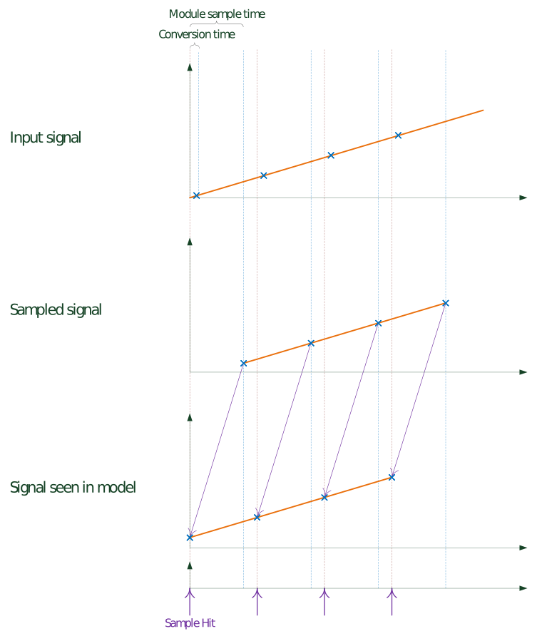
If the IO191 operates in non-DMA, a conversion starts with the driver block
generating a Sample Hit. The driver block waits for the module to finish the
conversion of the Active Channels before reading the value and then starting a new
conversion.
DMA
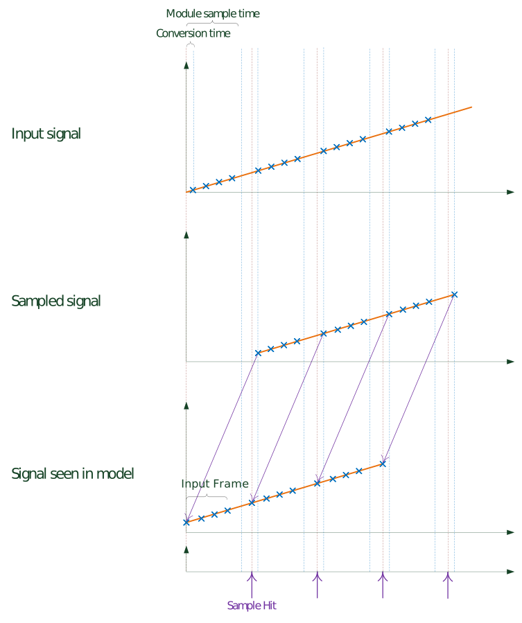
If the IO191 operates in DMA, conversions will occur at the rate configurated on
the ADC Rate (the sample rate is divided by the number of channels selected). The
driver block reads the latest frame data (Active Channels * Frame Size) from the
module on every Sample Hit. The Sample Hit are DMA interrupts generated by the
module. When the module sample time does not accord with the block sample time, this
can cause signal deformation.
DMA Setup
If DMA is enabled for Analog inputs, the model or the asynchronous subsystem where
the module is located has to be triggered by the module's interrupt. The module's
interrupt is necessary so the sample hits of the blocks are synchronous to the
module's DMA engine.
In DMA mode, the model must contain an Interrupt Setup block that triggers a
subsystem or the model. Refer to the block documentation for more
information.
Programmable Input Range
The IO191 uses the ADAS3022 which incorporates a programmable gain instrumentation
amplifier with seven selectable ranges (±0.64 V, ±1.28 V, ±2.56 V,
±5.12 V, ±10.24 V, ±20.48 V and, ±24.576 V), enabling the use of
almost any direct sensor interface. The input range settings are specified in terms
of the maximum absolute differential input voltage across a pair of inputs (for
example, Ch 1+ to Ch 1−). Note that because the IO191 can use any input type, such
as differential or single-ended, setting the mode is important to make full use of
the input span available.
These usage notes provide some examples of setting the mode in differential to be
able to use ±20.48 V or ±24.576 V. Note that the ADAS3022 always
calculates the difference between the Ch # + and Ch # − signals.
Example: Differential signals with a non-zero DC
offset
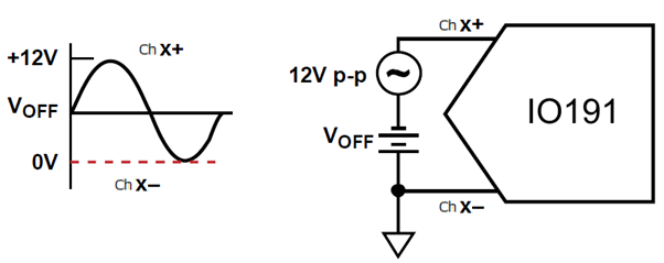
When a 12 V p-p signal with a 3 V DC level-shift is connected to one channel (Ch x
+) and the DC ground sense of the signal is connected to Ch x−, the input range
configuration is set to a ±20.48 V or ±24.576 V range because the maximum
differential voltage across the inputs is 12 V p-p and only half the codes available
for the transfer function are used.
Example: Antiphase signals with a zero
common
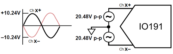
With a pair of 20.48 V p-p differential antiphase signals in zero-common mode,
when the input range configuration is set to ±20.48 V or ±24.576 V, the
maximum differential voltage across the inputs is ±20.48 V.