IO191 Pin Mapping
IO191 Pin Mapping —
Reference information about the I/O module connector
Front Connector A Pin Mapping
![[Warning]](images/warning.png) | Warning |
|---|
The maximum voltage applied to any single pin in analog input is ±12 V. |
![[Important]](images/important.png) | Important |
|---|
Unused analog input pins must be connected to Analog Ground. 0 V is internally connected to the ground of the target machine, whereas
analog ground is connected to the ground of the I/O module. 5 V are supplied by
the real-time target machine, which is capable of providing 1 A continuous
current. For more information, refer to the real-time target machine user
manual. |
Front Connector B Pin Mapping
| Important |
|---|
The Digital Ground pin is connected to the ground of the target machine
through the I/O module. |
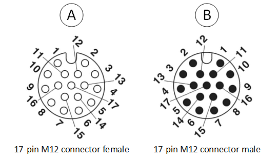
M12 Connector Pin Mapping