IO104 Usage Notes
IO104 Usage Notes — Usage information about the
I/O module
Description
This section offers some detailed descriptions of common use cases for the IO104.
Continuous Frame Based Closed-Loop
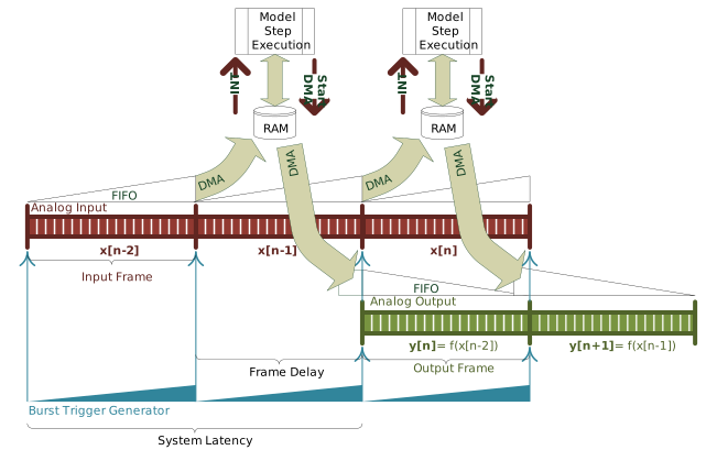
In this configuration, the burst trigger generator paces both input and output
bursts. The Simulink model is driven by the "IO104 DMA INT" interrupt, so the
execution is started shortly after the trigger signal.
With synchronized input and output frames we get a constant system latency of
exactly two frame times.
The output signal will have no discontinuities or
gaps.
DMA Operation
Interrupt driven execution
In DMA mode, the model must contain an
Interrupt Setup block that triggers a subsystem or the model. Refer to the block
documentation for more information.
Interrupt Source
The interrupt is always generated by the Analog input block's DMA completion. If
that block is not present in the model, the driver uses a dummy input acquisition in
the background.
Interrupt Timing and Latency
The interrupt is issued a few microseconds after the analog input has completed
the sampling of one frame.
In continuous sampling mode (sampling time x frame size = frame time)
the interrupt is issued a few microseconds after the trigger signal,
when the last samples are transferred to memory. As the interrupt is
starting the model execution, you should make sure that the Analog input
block is the first block to be executed and that the Analog output block
is executed before the next trigger occurs. Like this, a closed-loop
operation with a precise latency of two frames times can be
realized.
When the frame size is much smaller than what would fit into one frame
time, only one sample for example, we can achieve a precise latency of
only one sample.
Execution Time Estimation
The time needed by the driver to bring DMA data to the Analog input's output ports
can be calculated like this: t = frame_size * number_of_channels * 4.046ns
The time needed by the driver to read the Analog output's input ports and send
them to the DMA channel can be calculated like this: t = frame_size *
number_of_channels * 3.647ns
These factors apply to a speedgoat performance real-time target machine running at
3.5GHz in multicore mode.
Synchronisation
The analog inputs, analog outputs and the frame burst trigger can all be
configured independently as either initiators or targets.
An initiator can be connected to up to four targets.