Serial Usage Notes
Serial Usage Notes — Usage information for onboard
COM ports as well as serial I/O modules and code modules
Usage Notes
Serial communication on Speedgoat real-time target machines is enabled as
follows:
Onboard COM ports: motherboards used in
most of the target machines include one or more COM serial ports, featuring
a 9-pin D-sub connector. The pin mapping is included in the target machine
user manual. These ports typically offer a limited baud rate (115 kbps)
and software configuration options, and are intended for slow, asynchronous,
non-cyclic communication (for example, read inputs from a terminal). The
buffer is limited to a few bytes, so they are not appropriate for long
messages
Serial I/O modules: these are dedicated
I/O modules designed for robust serial communication. They are fully
software configurable and support higher baud rates. The driver construction
can be optimized to accommodate various use cases, including cyclic
communication at fast sampling rates
Code modules: specific serial
communication can be integrated into a configuration file for the
configurable I/O modules or used in HDL Coder models using the Communication
HDL I/O Blockset. Code modules can be customized to achieve very specific
baud rates and meet special buffer sizes. Transceivers cannot be modified,
and some special wiring requirements may not be supported
RS422/RS485 Wiring Examples
The RS422 and RS485 protocols use differential transceivers. When using long
cables, it is important to terminate the lines appropriately, to avoid data
reflection. A few examples are provided below of the most common
configurations.
Serial I/O modules may allow software configuration of the termination resistors
and onboard COM ports, and FPGA I/O modules may or may not have termination
resistors and options. Please refer to the specific target machine or I/O module
user manual.
RS422 Multidrop
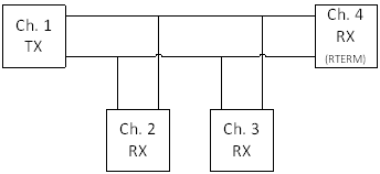
RS422 Multidrop configuration consists of one channel transmitting to multiple
receivers. The transmitting node does not require a termination resistor. The
receiving node at the end of the line does however require a termination
resistor.
Some I/O modules have termination resistors that cannot be enabled/disabled
and therefore may not be appropriate for multidrop configuration. Some drivers
include "RS422 Multidrop" for the Transceiver Setup parameter.
RS422 Full-Duplex Point-to-Point
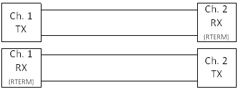
Full-duplex communication means that each node can receive and transmit data
at the same time. Separate TX and RX channels are used. The termination resistor
is required at the end of the line. Some drivers include "RS422 full duplex" or
"RS422" for the Transceiver Setup parameter.
RS485 Full-Duplex Point-to-Point
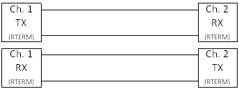
For RS485, the termination resistor is required on both ends. Some drivers
include "RS485 full duplex" for the Transceiver Setup parameter. If there is an
option for "RS485 turnaround", it must be enabled.
RS485 Half-Duplex Point-to-Point
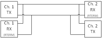
Half-duplex configuration allows bytes to be sent and received on the same
node, but not at the same time (the sender and receiver are mutually excluded).
In this case, the termination resistor is required at the receiver side only.
Some drivers include "RS485 half duplex" for the Transceiver Setup parameter. If
there is an option for "RS485 turnaround", it must be enabled.
Sampling Time
When we use serial communication, by definition, nodes are transmitting and
receiving bytes one after the other.
In most cases, the message frame length will set the minimum sampling time for
sending a new message. To configure the receiving sampling time, it is also
important to consider the delay between two messages. It is important that the
buffer is read faster than the minimum delay, to ensure that no messages are
missing.
The message frame length is defined as follows and depends on the baud rate
expressed in bits per second (bps):

For simple RS232/RS422/RS485 communication, data bytes have one start bit and one
or two stop bits. Consequently, the number of data bytes is multiplied by 10 (or 11)
instead of 8 bits.
Example

This means that a 32-byte message at 230400 bps will physically take 1.4 ms on
the serial line. The main consequence of this result is that after sending this
message, 1.4 ms at the very least must elapse before another message is sent on
the line.
If the buffer size is smaller than the message size, then we must also
consider the time required to flush the buffer. This will introduce an
additional delay (typically about a few tens of microseconds, depending on the
I/O module).
It is also important to consider cable length and other nodes on the line
which may also transmit other messages (or send responses).
The sampling time of the transmitter side must eventually be slow enough to
accommodate the above requirements.
Polling Mode
Code modules support polling. In this case, the hardware driver blocks are used
without requiring the software FIFO blocks or interrupts.
Data transmission: the data is sent directly to the hardware buffer at a defined
sample time.
Data reception: the hardware buffer block is read at a regular sample time, fast
enough to avoid missing data.
Depending on the specific use case, it may be possible to optimize the
construction; for example, data could be sent using the hardware FIFO and received
with interrupts and software FIFO blocks to ensure full synchronization.
Legacy Mode
When activating the legacy mode for a specific read or write block, the first element of the data in-/output vector contains
the information about the size of the payload in bytes. The following is an example
of a possible input configuration:
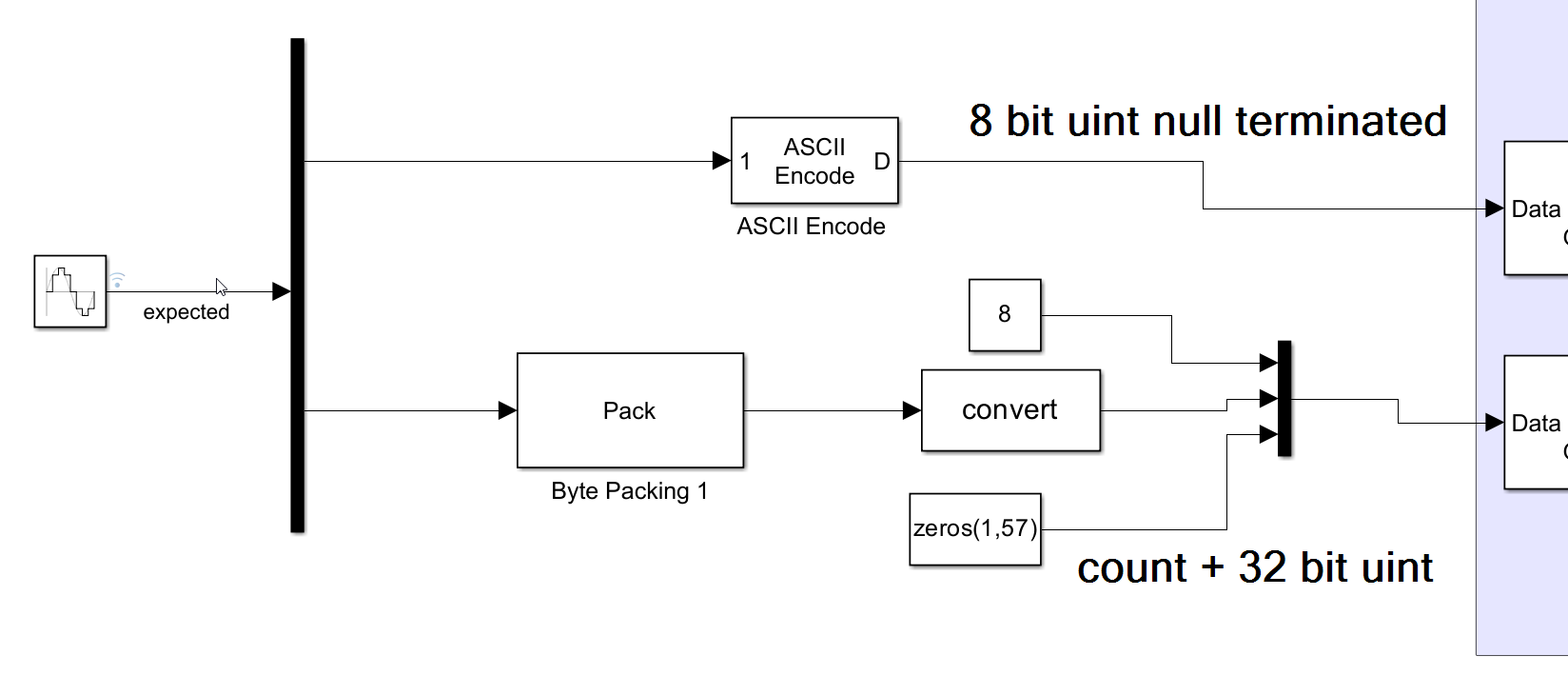
Without legacy mode the read and write blocks use two different ports. The count
port gives or receives information about the payload size, such as the first element
in a vector when using the legacy mode.
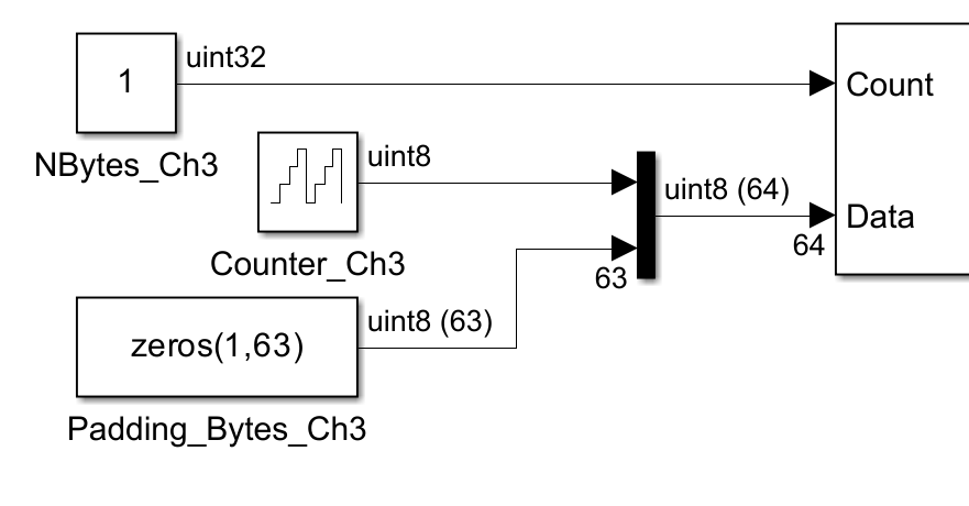
The input or output port widths must always be the same size as the FIFO buffers
defined in the Simulink block mask. To achieve the same length, even if the payload
is less, the rest of the buffer must be filled up with zero padding bytes (as seen
in the pictures above).
Utilities
The Simulink Real-Time/RS232 library provides utilities blocks that can be used in
combination with the send and receive blocks.
Examples can be found in the MathWorks help documentation for Simulink Real-Time.
The library and examples refer to "RS232" but can also be used for any other
serial communication protocol.
Detailed information about serial communication using Simulink Real-Time is
available in the following online application notes:
Where can I find information about serial communication using
Simulink Real-Time?