SENT Usage Notes
SENT Usage Notes — Usage information about the
protocol and the code module
Protocol Description
SENT is a unidirectional communication standard where data from a sensor is
consecutively transmitted, without any intervention from the data receiving device.
A new transmission starts immediately after the previous transmission ends (the
trailing falling edge of the SENT CRC nibble is also the leading falling edge of the
next Synchronization/Calibration pulse).
One transmission consists of a series of pulses, where the time between
consecutive falling edges defines the 4-bit data nibble transmitted. The 4-bit data
nibble represents values 0 to 15. A SENT communication unit of time (tick) can be in
the range 3 µs to 90 µs. The maximum clock variation allowed for the sensor is ±20 %
from the nominal tick time.
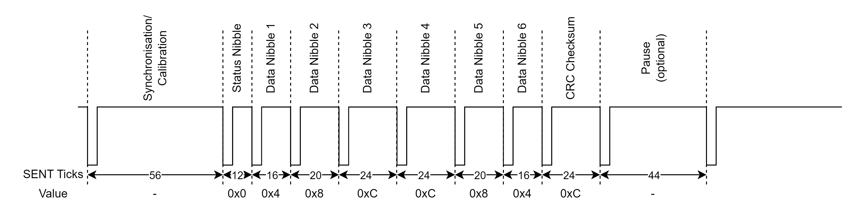
The transmission sequence consists of the following pulses:
Calibration/Synchronization pulse (56 tick times)
4-bit Status nibble pulse (12 to 27 tick times)
A sequence of two to six 4-bit Data nibble pulses (12 to 27 tick times
each)
4-bit Checksum nibble pulse (12 to 27 tick times)
One optional pause pulse (12 to 768 tick times)
Synchronization/Calibration Pulse
The SENT specification allows a ±20 % clock deviation from the nominal unit
time, the Synchronization/Calibration pulse provides information on the current
transmitter tick period. The time between the falling edges of the
Synchronization/Calibration pulse defines 56 ticks. The SENT RX can calculate
the current unit time period of the sensor from the pulse width and can
therefore resynchronize on each start of a frame.
Status Nibble Pulse
The Status nibble contains 4-bit status information on the sensor and it is
also used to transmit enhanced serial messages (see below for more information).
The width of the Status nibble pulse depends on the nibble value.
Data Nibble Pulse
A single data nibble pulse carries 4-bit data. A maximum of 6 data nibbles can
be transmitted in one SENT transmission. The total number of data nibbles
depends on the protocol used by the sensor. The width of the data nibble pulse
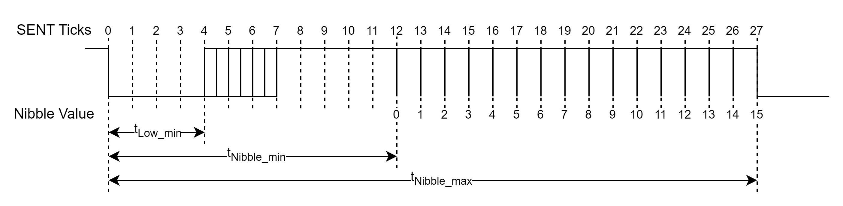
depends on the nibble value. The next figure depicts the format of the data
nibble pulse. The pulse starts with the falling edge and remains low for at
least four ticks. The remainder of the pulse width is driven high. The total
data pulse width in the number of unit times is defined by the following
equation: Data Nibble Pulse Width = 12+Nibble Value
Checksum Nibble Pulse
The checksum nibble contains a 4-bit CRC value. The checksum is calculated
using a
x4+x3+x2+1
polynomial with the seed value of 5 (0b0101) and the reset value of 3
(0b0011).
For older devices (2008 and earlier), the legacy CRC generation was used where
all but the last data nibbles are calculated through the CRC polynomial and the
last data nibble is only bitwise XOR operated with the CRC result of the
previous data nibbles.
Newer devices use the recommended CRC generation where all data nibbles are
calculated through the CRC polynom.
Pause Pulse (optional)
At the end of each frame, an optional pause pulse can be added. The pause
pulse can vary between 12 ticks and 768 ticks.
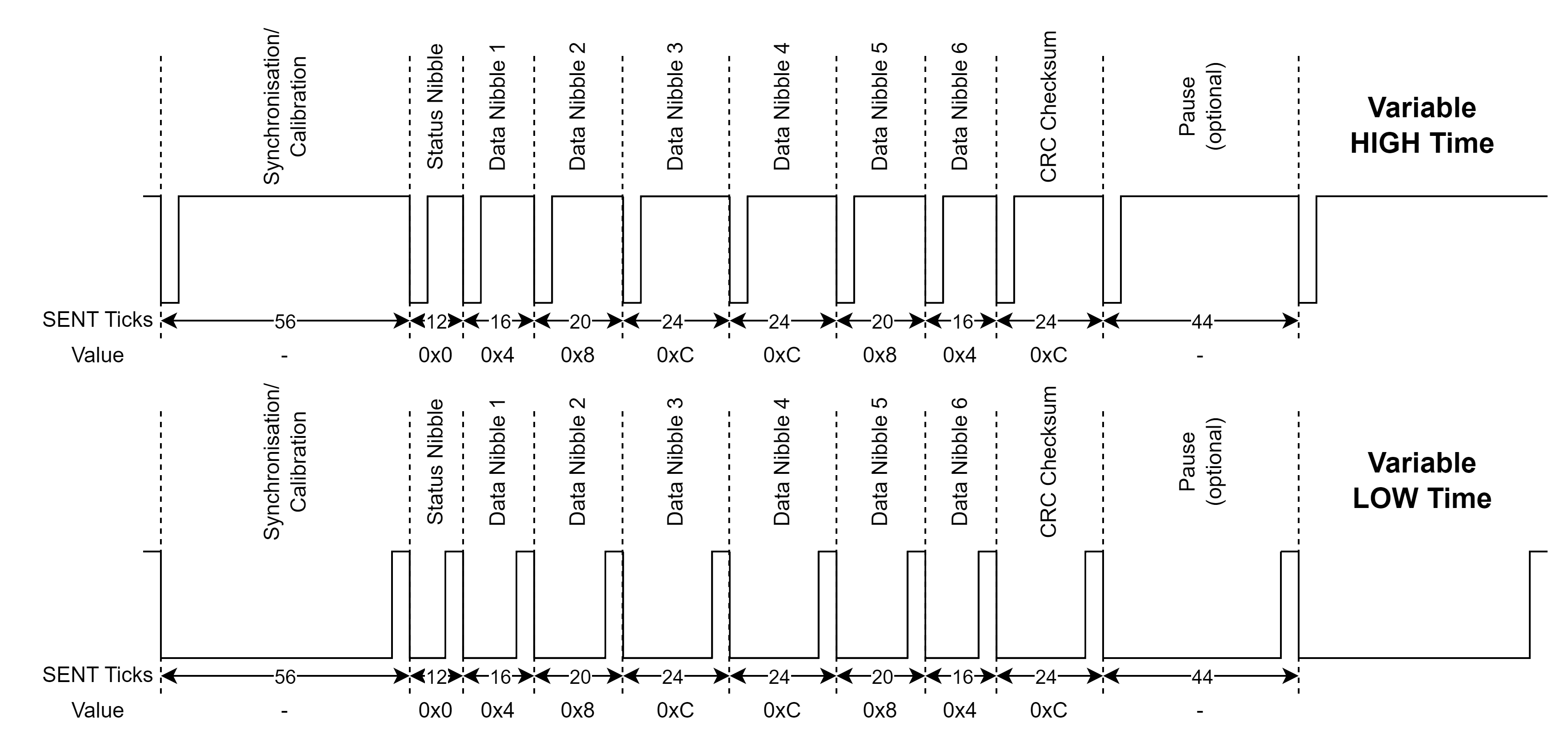
Variable LOW Time
Most devices keep the LOW time fixed and vary the HIGH time of the SENT
signal, as depicted above. Since the SENT standard only defines the minimum LOW
width of a pulse, there are also devices that keep the HIGH time fixed and vary
the LOW time instead:
SENT SPC
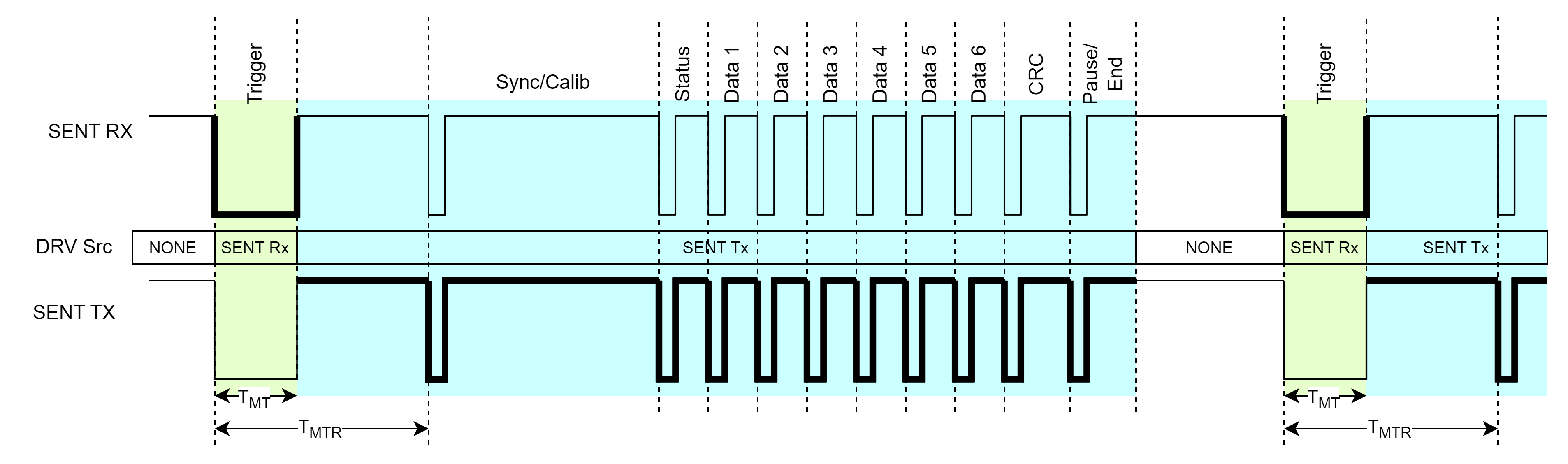
The SPC protocol enhances the SENT protocol by introducing a half-duplex
synchronous communication. To initiate a transmission, the receiver device generates
a Trigger pulse (green part in in the next Figure) by driving the communication line
LOW for a defined amount of time (tMT). The transmitter
device measures the pulse width and only responds if the pulse width is within
defined limits (see Master Pulse Requirements).
When the transmitter responds, it starts driving the line HIGH until
tMTR is reached. The transmitter continues driving the
SENT signal (blue part in the next Figure). A pause pulse is also transmitted in
order to provide a trailing falling edge for the CRC nibble pulse. The transmitter
then stops driving the communication line and the receiver is able to generate a new
Trigger pulse. The figure below depicts the SENT SPC frame format:
Master Pulse Requirements
There are several types of SPC initiations which are described in the
following chapters.
Synchronous Transmission Including Range Selection
The low time duration of the synchronization pulse can be used to select the
magnetic range of the sensor in SPC dynamic range selection mode:
Synchronous Mode with ID Selection
This functionality is similar to the previous mode, but instead of switching
the range of one sensor, one of up to four sensors can be selected on a bus (1
master with up to 4 slaves). This allows the parallel connection of up to 4
sensors using three lines only. In this mode, the sensor starts to transfer a
package only after a master low pulse, including its ID, have been
received.
Enhanced Serial Message (Slow Message)
If the enhanced serial message format is used (also called Slow
Message), serial data is transmitted in the bits 3 and 2 of the
status nibble. An enhanced serial message frame stretches over 18 consecutive SENT
data messages from the transmitter as shown in the next figure. All 18 frames must
be successfully received (no errors, calibration pulse variation, data nibble CRC
error, etc. are allowed). The frame start of a serial message is indicated by the
"01111110" unique pattern in bit 3 of the status nibble (SENT messages #18, and #1
to #7). Two different configurations are available depending on the configuration
bit (serial data bit #3, serial communication nibble No. 8, marked blue in the next
Figure):
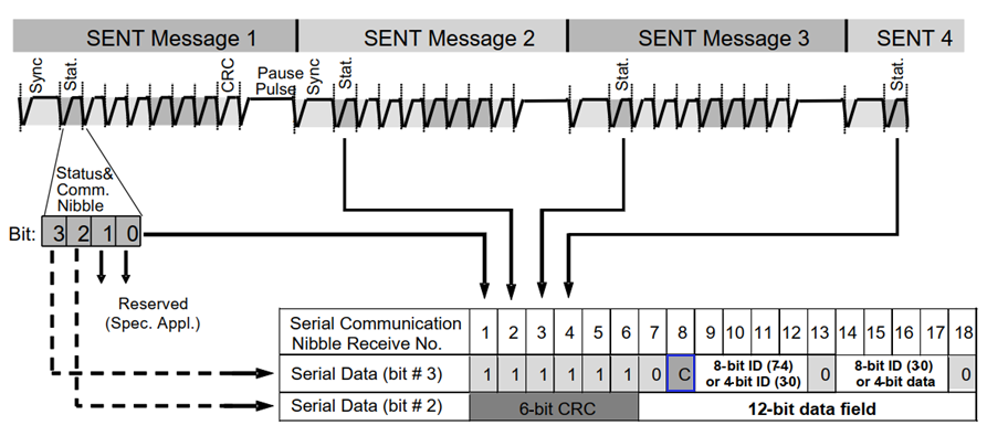
All data (data field, message ID and CRC) transmitted in the serial message
channel is sent in the following order: MSB (most significant bit) to LSB (least
significant bit).
Enhanced Serial Message CRC
For frames 7-18, the CRC value is computed as a function of the contents of
Serial data message bits #2 and #3. For the purpose of the CRC calculation, the
bits are ordered as shown in the following figure.
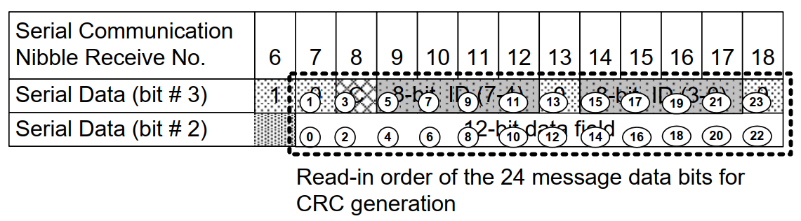
The encoding is defined by the 6-bit wide generating polynomial,
x6+x4+x3+1
and the seed value of 21 (0b010101) and the reset value of 59 (0b111011).