SENT - SENT Rx v1
SENT - SENT Rx v1 — The SENT Rx receives data accordingly
to SAE J2716 protocol.
Library
Simulink Real-Time - Speedgoat
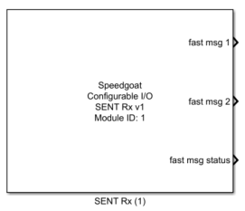
Description
The SENT Rx block receives fast and enhanced serial messages over the SAE J2716
protocol.
Ports
The Simulink block has up to 8 outputs ports, depending on the
configuration:
Outputs
-
fast msg 1
This port is only visible when SENT Data
Format is set to anything else than Custom
Protocol.
This port represents the first fast message (channel 1) of the SAE
J2716 protocol. Data is aligned on the LSB (bit 0).
-
fast msg 2
This port is only visible when SENT Data
Format is set to either H1, H4, H6 or
H7.
This port represents the second fast message (message channel 2) of
the SAE J2716 protocol. Data is aligned on the LSB (bit 0).
In case SENT Data Format is set to
H4, this port represents the secure sensor
information whereas the lower 4 bits (b0 to b3) of this port represent
the inverted nibble3 of the first fast message and the bits b4 to b11
represent the rolling counter.
-
fast msg
This port is only visible when SENT Data
Format is set to Custom
Protocol.
This port represents the custom fast message that can be 8 to 32 bits
length. Data is aligned on the LSB (bit 0).
-
fast msg status
This port is only visible when Show fast msg
status is set.
This port represents the SENT Status bits 1 and 0.
-
fast msg error status
This port is only visible when Show fast msg
error status is set.
This port represents detailed error information about the SENT
Receiver state. The following table describes the register more in
detail. A fast message is only valid when this port value is 0.
-
fast msg valid cntr
This port is only visible when Show fast msg
valid cntr is set.
This port represents the number of successfully received fast
messages. The value is a 16-bit unsigned integer that overflows.
-
fast msg error cntr
This port is only visible when Show fast msg
error cntr is set.
This port represents the number of erroneous received fast messages.
The value is a 16-bit unsigned integer that overflows.
-
serial msg ID
This port is only visible when Show Enhanced
Serial Message is set.
This port represents the ID of the last successfully received serial
data message.
-
serial msg data
This port is only visible when Show Enhanced
Serial Message is set.
This port represents the data of the last successfully received serial
data message.
-
serial msg error cntr
This port is only visible when Show Enhanced
Serial Message is set.
This port represents the number of serial messages where the unique
pattern 0b1111110 was received during the first 7 fast messages of an
enhanced serial message but one of the following 11 fast messages was
erroneous. The value is a 16-bit unsigned integer that overflows.
Parameters
Tab: Module setup
-
Configurable I/O Module ID
This parameter associates a code module block with a configurable I/O module setup
block. Set this value to match the Module ID defined in the setup block of the
required configurable I/O module.
-
Channel Vector
A vector of channels this driver block entity will access. You can specify
channels in the range 1-N (N = the number of channels implemented in your specific
configuration file defined in the Setup block). The width of this vector also
defines the subsequent size of some of the following parameters if scalar expansion
applies. With a single block, all the channels of the block are synchronized.
-
Sample Time
Defines the base sample time at which this driver block gets its sample hit. This
parameter can also be set to -1 for inherited
sample time. The units are in seconds.
Tab: SENT
-
Tick Length Vector
Defines the transmitter-specific unit time (time of one SENT tick)
between 1 microsecond and 90 microseconds. The units are in seconds.
This parameter is used for the following SENT receiver
operations:
Detection of a valid sync-pulse
In case the SENT receiver detected a pulse with length =
56* Tick Length (±20 %), a
new frame SENT frame reception starts
SPC signal generation
For any SPC Mode except
Disabled, this parameter is used to
generate the correct SPC pulse.
-
SPC Mode
Defines whether SENT SPC is disabled or which SPC mode is used.
Following settings are available (See SAE J2716 protocol for
details):
Disabled
Synchronous
Synchronous with range selection (range = 200 mT)
Synchronous with range selection (range = 100 mT)
Synchronous with range selection (range = 50 mT)
Synchronous for ID 1
Synchronous for ID 2
Synchronous for ID 3
Synchronous for ID 4
- SENT Data Format
Defines the Data format of the messages to decode.
Two 12-bit fast channels, fast message 1 and fast message 2
(H.1)
One 12-bit fast channel, fast message 1 only (H.2)
High-speed with one 12-bit fast channel, fast message 1 only
(H.3)
Secure sensor with one 12-bit fast channel, fast message 1 and
secure sensor information on fast message 2 (H.4)
Single sensor with one 12-bit fast channel, fast message 1 and
zero value on fast message 2 (H.5)
One 14-bit channel, fast message 1 and one 10-bit channel,
fast message 2 (H.6)
One 16-bit channel, fast message 1 and one 8-bit fast channel,
fast message 2 (H.7)
Custom Protocol, one fast message, selectable data width using
the parameter Number of Data
Nibbles
-
Enable Pause Pulse
This parameter is only visible when SPC
Mode is set to Disabled.
When set, a pause pulse is expected after the CRC nibble. If no pause
pulse was generated by the corresponding SENT TX source, a pulse count
error will occur. The pulse count error can be measured using the output
port fast msg error status.
-
Enable Raw Mode
When set, the output ports fast msg
show the latest received fast messages even if the frame was erroneous.
When not set, the output ports only show the latest received fast
messages that were valid.
- CRC Calculation Type
Defines the calculation type of the checksum of the fast
message
Recommended CRC:
All data nibble values are passed through the CRC calculation.
This result is compared to the received CRC checksum.
Legacy CRC:
All but the last data nibble values are passed through the CRC
calculation. This temporary checksum is binary XOR processed
with the last data nibble and then compared to the received CRC
checksum.
- Include Status Nibble
When set, the status nibble value will be included in the CRC
calculation. When not set, the CRC calculation is only based on the fast
messages data values.
- Use Default CRC Configuration
When set, the value of the CRC polynomial is set to the default value
x4 + x3 +
x2 + 1 and the CRC initial value is set
to 0b0011 as defined by the SAE J2716 protocol. When not set, the
Polynomial Vector and the Init Vector can be used to set a
user-specific CRC calculation
- Polynomial Vector
This parameter can only be set to a specific value when Use Default CRC Configuration is not
set.
The SENT protocol uses a 4-bit CRC calculation. This parameter
therefore is a 4-bit value that builds the CRC polynomial as following:
x4 + Bit3*x3 +
Bit2*x2 +
Bit1*x1+ Bit0
- Init Vector
This parameter can only be set to a specific value when Use Default CRC Configuration is not
set.
This parameter defines the initial value of the CRC
calculation.
![[Note]](images/note.png) | Note |
|---|
The SAE J2716 protocol defines a seed value
that is not the same. The initial value is the
CRC checksum of the seed value only. For example, using the standard SAE J2716 CRC Polynomial
x4 + x3 +
x2 + 1, the seed value 0b0101 will
generate a CRC checksum of 0b0011, therefore 0b0011 is the
corresponding initial value. |
Tab: Output Port Configuration
-
Show Enhanced Serial Message
When set, the output ports serial msg
ID, serial msg data and
serial msg error cntr will be
available to read the enhanced serial message (also called slow
message).
-
Show fast msg status
When set, an additional output is available to read the fast message
status bits 1 and 0.
-
Show fast msg valid
When set, an additional output is available to read the fast message
valid signal.
-
Show fast msg valid cntr
When set, an additional output is available to read the number of
valid fast messages received.
-
Show fast error cntr
When set, an additional output is available to read the number of
erroneous fast messages received.