Resolver Measurement
Resolver Measurement — The Resolver Measurement
driver block allows users to read the speed and position of a resolver with the
IO3xx-24 I/O interface extension.
Library
Simulink Real-Time - Speedgoat
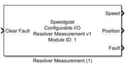
Description
The Resolver Measurement driver block allows users to read the speed and position
of a resolver with the IO3xx-24 I/O interface extension. The module contains two
Resolver-to-Digital Converter (RDC) chips including signal conditioning circuitry.
The RDC chips can be parameterized by this driver block, which will output the
measured speed and position.
Ports
The width of all the inputs and all the outputs is equal to the number of enabled
Resolver Measurement channels.
Inputs
-
Clear Fault
A logic high signal at this input port initializes a clear fault
register sequence of the resolver measurement interface. The fault
register is reset to zero. The data type of this input is
boolean.
![[Note]](images/note.png) | Note |
|---|
If the fault output remains non-zero after a clear fault request,
this means that the fault state persists. . |
Outputs
-
Speed
The measured resolver position in RPS (Revolutions Per Second). The
data type is double.
-
Position
The measured resolver position in degrees. The data type is
double.
-
Fault
The 8-bit fault register of the RDC. The converters indicate different
fault states based on the state of operation and the signal quality at
the interface to the resolver. The meaning of each bit is indicated in
the following table. The data type of the output signal is uint8.
Parameters
Tab: Module Setup
-
Configurable I/O Module ID
This parameter associates a code module block with a configurable I/O module setup
block. Set this value to match the Module ID defined in the setup block of the
required configurable I/O module.
-
Channel Vector
A vector of channels this driver block entity will access. You can specify
channels in the range 1-N (N = the number of channels implemented in your specific
configuration file defined in the Setup block). The width of this vector also
defines the subsequent size of some of the following parameters if scalar expansion
applies. With a single block, all the channels of the block are synchronized.
-
Sample Time
Defines the base sample time at which this driver block gets its sample hit. This
parameter can also be set to -1 for inherited
sample time. The units are in seconds.
-
Resolver Sample Trigger
Selects the trigger source to sample the speed and position of the
RDC. Speed and position are sampled simultaneously and then transferred
to a register in the FPGA from where they are accessible for the driver
block.
I/O module digital I/O:
The resolver speed and position are sampled based on one of
the digital I/O signals defined in the pin mapping of the
selected configuration file in the IO3xx Setup block. Any
digital I/O pin can be selected regardless of its assigned
functionality and direction. The additional parameters
Trigger edge and
External trigger are
visible when this option is selected.
Free running: Continuous
sampling of speed and position and data transfer to the
FPGA. The driver block outputs the latest available
values.
Model step: The execution
of the Resolver Measurement driver block triggers a new
sample of speed and position each model sample step. The
speed and position outputs at model step n represent the
sampled speed and position from model step n-1.
-
Trigger Edge
Defines on which edge of the selected digital I/O signal the speed and
position are sampled.
Rising edge
Falling edge
Rising and falling edge
-
External Trigger (Digital I/O Channel)
Defines the digital I/O channel for the resolver measurement sample
trigger. The value must fall in the range of the available Digital I/O
channels. This information can be found in the pin mapping of the
selected configuration file in the IO3xx
Setup block. The digital I/O channel numbers are
indicated in the pin mapping of the configuration file. The edit field
accepts scalar values (same value applies for all active channels) or a
vector with the number of elements equal to the number of enabled
Resolver Measurement channels.
Tab: Resolver Measurement Channel 1 and 2
Each Resolver Measurement channel can be configured independently in its
corresponding tab.
-
Resolution vector [bit]
The RDC can operate in four different resolution modes. The resolution
also determines the maximum speed which the device can track:
10-bit (maximum tracking rate: ±3125 rps)
12-bit (maximum tracking rate: ±1250 rps)
14-bit (maximum tracking rate: ±625 rps)
16-bit (maximum tracking rate: ±156.25 rps)
-
Excitation frequency vector [kHz]
Defines the frequency of the sine wave at the excitation output. The
frequency must be within the range of 2 kHz to 20 kHz.
-
Excitation voltage vector [Vrms]
Defines the RMS voltage of the differential sine wave signal at the
excitation output. The range is between 2 V and 12 V. The edit field
accepts integer values only.
-
Input voltage vector [Vrms]
Defines the input voltage of the modulated sine and cosine
differential signals coming from the resolver. The value refers to the
peak amplitude at 0 degrees (cosine) and 90 degrees (sine). The input
signal conditioning circuit is configured according to this parameter.
Set the input voltage based on the selected Excitation voltage and the transfer ratio of the
connected resolver. The range is between 2 Vrms and 12 Vrms. The edit
field accepts integer values only.
Tab: Input and Output Port Configuration
-
Show Speed Output
When this parameter is set, the Speed
output of the block is visible.
-
Show Position Output
When this parameter is set, the Position output of the block is visible.
-
Show Fault Register Output
When this parameter is set, the Fault
output of the block is visible.
-
Show Clear Fault Input
When this parameter is set, the Clear
Fault input of the block is visible.