Modbus - Client Send
Modbus - Client Send — Sends the data on the input
port to the remote server.
Library
Simulink Real-Time - Speedgoat
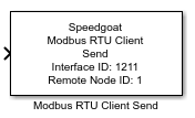
Description
This block is used to send data to the remote Modbus RTU Server.
You can use multiple Modbus RTU Client Send blocks for each Modbus RTU client node
configured in your model.
Ports
Inputs
-
TX
Array of length Quantity that
includes the values to be sent to the Modbus
Server for the data range specified by the Index and Quantity parameters. The data type depends on the
selected function code.
For Coils and Discrete Inputs, the input port is a vector of
the BOOLEAN data type, where the length of the vector is defined
by the Quantity parameter. Each
BOOLEAN element of the vector represents one bit.
For Holding Registers and Input Registers, the input port is a
vector of the UINT16 data type, where the length of the vector is
defined by the Quantity
parameter. Each UINT16 element of the vector represents one
word/register.
Use Byte Pack blocks to convert signed values or floating-point
numbers. You can pack one double value to a vector of type UINT16 and
length 4.
-
ENA
Boolean input to allow the user to manage the handling of Modbus
requests to the defined Modbus Server. This input is only active if the
Manage Requests checkbox is enabled.
Send a boolean value of 1 to enable sending or 0 to disable the sending
of Modbus requests. If the sending is stopped, the Send block will still
be able to receive the response message.
Parameters
-
Client Interface ID
Apply the Client Interface ID of the corresponding Setup block. Must
range between 0 and 65535.
-
Remote Server Node ID
Enter the Node ID of the remote Modbus RTU server. You can use
multiple Receive blocks to exchange data with that server. Must range
between 0 and 247. Setting the Node ID to 0 will address all Modbus RTU
servers on the serial line!
According to the Modbus standard, unit ID 255 means NON-SIGNIFICANT.
When addressing a Speedgoat Modbus Server and the node identifier is set
to 255 but unit 255 is not configured in the server itself, the
requested command is performed on the first unit specified in the server
configuration.
-
Function Code
Select the Modbus Function Code you want to use for your
communication. The options are:
FC5 (Write Single Coil)
The input will be a single uint16.
FC6 (Write Single Holding Register)
The input will be a single uint16.
FC15 (Write Multiple Coils)
The input will be an array of uint16.
FC16 (Write Multiple Holding Registers)
The input will be an array of uint16.
Refer to the Modbus usage notes
for further information about function codes.
-
Data Index
The first index of the data range you want to send or receive. Must
range between 0 and 65535.
For Coils and Discrete Inputs, the parameter defines the start
bit.
For Holding Registers and Input Registers, the value defines
the start word.
-
Data Quantity
The length of the data range you want to send or receive. Index + Quantity must not exceed 65536.
-
Swap Bytes
The bytes of a register must be swapped if the sender and the receiver
interpret the byte order in different ways (endianness). The Speedgoat
real-time target machine uses little-endian, while some clients use big-endian.
If the swap option is enabled, all register values from the
application context will be swapped before they are sent to the network.
All register values received from the network will be swapped before
they are submitted to the application context. The swap option only
affects input registers and holding registers (transmitted by function
codes FC3, FC4, FC5, FC6, FC16). Discrete inputs and coils are not
affected. Use Byte Reversal blocks instead of enabling the global byte
swapping if only single registers need to be swapped.
-
Polling Interval
The polling Interval is the time interval between sending Modbus
requests to the server. Must range between 0 and 7,200,000 milliseconds,
which corresponds to a maximum of 2 hours.
-
Manage Requests
Tick this checkbox if you want to control sending Modbus requests.
This activates the ENA input port of
the Send block. If the sending is stopped, the Send will still be able
to receive the response message.
-
Sample Time
Defines the base sample time at which this driver block gets its sample hit. This
parameter can also be set to -1 for inherited
sample time. The units are in seconds.