Modbus Usage Notes
Modbus Usage Notes — Detailed information about the
Modbus protocol and the Modbus blockset
Introduction to Modbus
Modbus communication protocol that allows interoperability between components
mostly in electric grids and automation plants. These components are either client
or server. One client accesses multiple servers to read and write data that the
server manages in 4 data tables:
Coils (bit values the client can read and write)
Discrete Inputs (bit values the client can only read)
Holding Registers (word values the client can read and write)
Input Registers (word values the client can only read)
Modbus TCP is a TCP/IP-based protocol. In Modbus TCP networks, each physical
device has a unique IP address. Servers normally listen on TCP port 502 for incoming
connection requests from clients. TCP port numbers on the client side are
random.
Modbus RTU is a widely used serial communication protocol. It operates over RS-485
(or sometimes RS-232) serial interfaces. In Modbus RTU, data is transmitted in
binary format, making it fast and reliable for communication between devices such as
programmable logic controllers (PLCs) and sensors.
For further information about the Modbus protocol, refer to the official online
Modbus documentation.
Runtime License
Modbus blocks require a runtime license installed on the target machine. Please refer to
the Runtime Licensing help.
Typical Target Machine Configurations - for Modbus TCP
For Modbus TCP communication with Speedgoat target machines, you can use onboard
Ethernet interfaces and plug-in Ethernet I/O modules.
Use the Ethernet Configuration Tool to assign IP addresses to these Ethernet
interfaces. Enter the following in the MATLAB command window to open the tool:
>> speedgoat.configureEthernet

For Modbus TCP, you can use any Ethernet interface when Configuration is set to IP
Protocols.
One real-time target machine can perform multiple Modbus TCP clients and servers.
There are four possible configurations:
- One IP Address per Ethernet Interface
One IP address is assigned to one Ethernet interface. This Ethernet
interface acts as either one Modbus TCP client or one Modbus TCP server
in the network. You can install multiple Ethernet I/O modules (providing
up to 4 interfaces each) or use additional onboard Ethernet interfaces
to set up multiple Modbus TCP clients or servers. As all the Ethernet
interfaces of a target machine must be associated with different
Ethernet subnets, each Modbus TCP station must operate in another
Ethernet network. If an application requires multiple clients to
communicate with different Modbus TCP networks, then this target
configuration is the correct choice. In contrast, if the simulation of a
Modbus TCP network with multiple servers is required, this setup cannot
be used.
The subnet dedication of an Ethernet interface is defined by IP
address and subnet mask.
- Multiple IP Addresses per Ethernet Interface (IP Aliasing)
IP aliasing can be used to assign multiple IP addresses to a single
physical interface. This allows multiple Modbus TCP clients and servers
to be operated on the same Ethernet I/O module or the same onboard
Ethernet interface. As the related IP addresses are always associated
with the same Ethernet subnet, this configuration is ideal for
simulating a Modbus TCP network containing multiple servers. Even mixed
operation (client and server) is possible for the purpose of loopback
testing. Alias addresses can be configured in the advanced settings of
the Ethernet Configuration Tool or by functions.
Enter the following in the MATLAB command window to manage IP
aliasing:
                                >> ipAliasObj = speedgoat.IpAliasConfiguration()
                                >> ipAliasObj.add('ETH2', {'192.168.10.31','192.168.10.32','192.168.10.33'})
                                >> ipAliasObj.remove('ETH2', {'192.168.10.33'})
                                >> ipAliasObj.add('Host Link', {'192.168.1.15','192.168.1.19'})
Enter the following in the MATLAB command window to check the available
Ethernet interfaces and configured IP aliases:
>> ipAliasObj.show()
                                Interface Name      IP Address          Subnet Mask
                                ---------------     ---------------     ---------------
                                ETH2                192.168.10.1        255.255.255.0
                                192.168.10.31       255.255.255.255
                                192.168.10.32       255.255.255.255
                                192.168.10.33       255.255.255.255
                                Host Link           192.168.1.14        255.255.255.0
                                192.168.1.15        255.255.255.255
                                192.168.1.19        255.255.255.255
- Multiple TCP Ports per IP Address
This is the normal operation for clients as each connection of the
client to a server requires a separate TCP port.
For server simulation, you can ignore the default server port 502 and
allow multiple servers to listen on different TCP ports. All these
servers will then act in the same subnet.
Typical Serial I/O Module Configuration - for Modbus RTU
UART Protocol Configuration
- The following values represent the standard settings for a serial
interface defined by the Modbus normative.
Modbus Data Exchange
Modbus data is exchanged in request-response fashion. The client sends a request
frame to the server. The server sends a response frame to the client. The server is
not allowed to send data autonomously.
The client request consists of
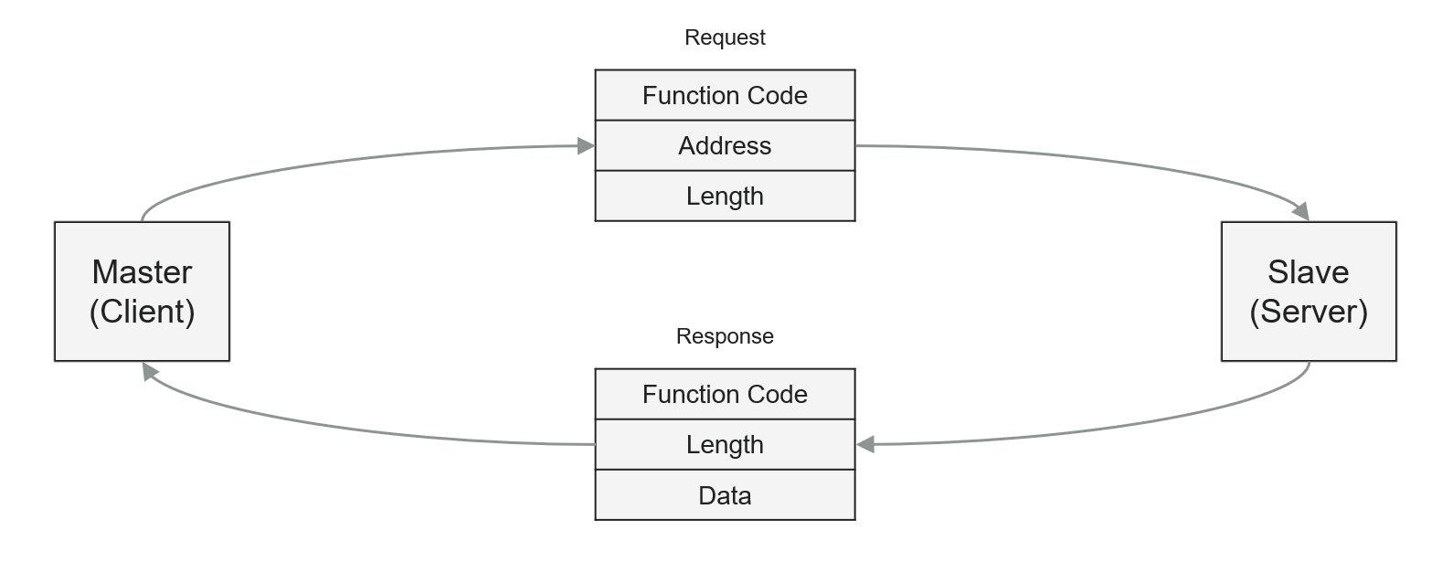
For read requests, the server sends a response to the client which contains the
original function code and the data which has been requested. For write requests the
server sends a simple confirmation containing the function code.
The following function codes are supported by the Speedgoat Modbus blocks:
FC1
FC2
FC3
FC4
FC5
FC6
FC15
FC16
In addition to the above list, the Modbus RTU Server also supports the diagnostics
FC8 with Subfunction 00.
Depending on the data area, there are two types of address and length
information:
Coils/Discrete Inputs: Bit address, Number of bits (bit-based)
Holding Registers/Input Registers: Word address, Number of words (16
bit-based)
In the following tables you can see how the four data tables are structured and
how bit- and word-addressing works. The Modbus addresses 0XXXX, 1XXXX, 3XXXX and
4XXXX are still commonly used to label Modbus TCP registers. They have been taken
over from serial Modbus RTU but serve no purpose in Modbus TCP addressing.
Detailed Description of supported MODBUS function
codes
FC1 (Read Multiple Coils):
The function code can read the status coils. The request message specifies
the starting address, meaning the Index of
the first coil specified, and the Quantity
of coils. In the message, Coils are addressed starting at zero. Therefore
the coils numbered 1-16 are addressed as 0-15.
FC2 (Read Multiple Discrete
Inputs)
This function code is used for reading from contiguous discrete inputs.
The request message specifies the starting Index, for example, the address of the first input
specified, and the Quantity of inputs. In
the message, Discrete Inputs are addressed starting at zero. Therefore the
discrete inputs numbered 1-16 are addressed as 0-15.
FC3 (Read Multiple Holding
Registers)
The function code is used for reading the content of a contiguous block of
holding registers. The request message specifies the starting register
Index and the Quantity of registers. In the message, Registers are
addressed starting at zero. Therefore the registers numbered as 1-16 are
addressed as 0-15.
FC4 (Read Multiple Input
Registers)
The function code is used for reading contiguous input registers. The
request message specifies the starting register Index and the Quantity of
registers. In the message, Registers are addressed starting at zero.
Therefore the input registers numbered 1-16 are addressed as 0-15.
FC5 (Write Single Coil)
This function code is used to write a single output to either On or Off.
The requested On/Off state is specified by a constant in the request data
field. A value of 0xFF00 requests the output to be On. A value of 0x0000
requests it to be Off. All the other values serve no purpose and will not
affect the output. Coils are addressed starting at zero. Therefore the coil
numbered 1 is addressed as 0.
FC6 (Write Single Holding
Register)
This function code is used to write a single holding register. The request
message specifies the Index of the register
to be written. Registers are addressed starting at zero. Therefore the
register numbered 1 is addressed as 0.
FC15 (Write Multiple Coils)
This function code is used to force each coil in a sequence of coils to
either On or Off. The request message specifies the coil references to be
forced. Coils are addressed starting at zero. Therefore the coil numbered 1
is addressed as 0.
FC16 (Write Multiple Holding
Registers)
This function code is used to write a block of contiguous registers. Data
is packed as two bytes per register (for example, 0xF5A1 - 16 bits).
Exception Responses
Function Codes
- In a normal response the server answers with the same function code as in
the request message. The indication of a present exception response means
that the server answer contains the function code but with its highest bit
set. All function codes have 0 for their most significant bit. Therefore,
setting this bit to 1 will indicate that the server cannot process the
request.
Exception Code Meaning
- The exception message contains the function code, and the exception code.
The exception code indicates the possible cause of the problem.