IO98X - Fault Insertion Control v2
IO98X - Fault Insertion Control v2 — Controls the
IO98X fault insertions
Library
Simulink Real-Time - Speedgoat
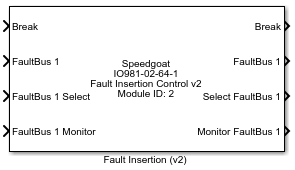
Description
The driver block used for configuring the driver is described in the following
sections.
Ports
General Information
All relays in the fault insertion module have a default state, which is defined
by the type of relay used.
The break relays are normally closed and all other relays are normally open.
All relays are in their default state between power-up and the first model
download.
During model execution, whenever one of the relays needs to be switched due to a
change on its input port, all relays go to their default state before the new state
is set.
Changes in v2
The channel relays no longer have separate input ports. "Break", "FaultBus 1" and
"FaultBus 2" are now vectors with the channels mapped according to the "Channel
vector" defined in the dialog fields.
Inputs
-
Break Type: boolean vector
Controls the break relay for all channels. The channel number n is
mapped according to the "Channel vector" defined in the dialog fields.
When the input value is '1', the relay connecting the IO pins M n and U
n is closed, '0' opens the relay.
-
FaultBus 1 Type: boolean vector
Controls the fault bus 1 relay for all channels. The channel number n
is mapped according to the "Channel vector" defined in the dialog
fields. When the input value is '1', the relay connecting the IO pin U n
to the fault bus 1 is closed, '0' opens the relay.
-
FaultBus 2 Type: boolean vector
Controls the fault bus 2 relay for all channels. The channel number n
is mapped according to the "Channel vector" defined in the dialog
fields. When the input value is '1', the relay connecting the IO pin U n
to the fault bus 1 is closed, '0' opens the relay. Some fault insertion
modules contain only one fault bus and therefore they do not show this
port.
-
FaultBus 1 Select Type: uint8
Selects which fault connection shall be connected to the fault bus 1.
The driver ensures that only one of the fault selection relays is closed
at any time. The port accepts integer values in the range 0 to the
number of supported fault inputs per fault bus. Here's an example for
modules with four fault inputs (F1, F2, F3, F4):
FaultBus 1 Select = 0: Relays F1, F2, F3 & F4 are
opened
FaultBus 1 Select = 1: Relay F1 is closed, F2, F3 & F4 are
opened
FaultBus 1 Select = 2: Relay F2 is closed, F1, F3 & F4 are
opened
FaultBus 1 Select = 3: Relay F3 is closed, F1, F2 & F4 are
opened
FaultBus 1 Select = 4: Relay F4 is closed, F1, F2 & F3 are
opened
FaultBus 1 Select = any other value: Relays F1, F2, F3 &
F4 are opened
Some modules have another number of fault inputs: adapt the example
accordingly.
-
FaultBus 1 Monitor Type: boolean
Controls the fault bus 1 monitor relay. When the input value is '1',
the relay connecting the IO pin MON1 to the fault bus 1 is closed, '0'
opens the relay. Some modules do not have monitor connections.
-
FaultBus 2 Select Type: uint8
Selects which fault connection shall be connected to the fault bus 2.
The driver ensures that only one of the fault selection relays is closed
at any time. The port accepts integer values in the range 0 to the
number of supported fault inputs per fault bus. Let's continue the
example with four fault inputs per fault bus:
FaultBus 2 Select = 0: Relays F5, F6, F7 & F8 are
opened
FaultBus 2 Select = 1: Relay F5 is closed, F6, F7 & F8 are
opened
FaultBus 2 Select = 2: Relay F6 is closed, F5, F7 & F8 are
opened
FaultBus 2 Select = 3: Relay F7 is closed, F5, F6 & F8 are
opened
FaultBus 2 Select = 4: Relay F8 is closed, F5, F6 & F7 are
opened
FaultBus 2 Select = any other value: Relays F1, F2, F3 &
F4 are opened
Some modules have another number of fault inputs: adapt the example
accordingly. Some fault insertion modules contain only one fault bus and
therefore they do not show this port.
-
FaultBus 2 Monitor Type: boolean
Controls the fault bus 2 monitor relay. When the input value is '1',
the relay connecting the IO pin MON2 to the fault bus 2 is closed, '0'
opens the relay. Some modules do not have monitor connections.
Outputs
-
Break Type: boolean vector
Monitors the state of the BREAK relay for all channels. When the relay
connecting the IO pins M n and U n is closed, the port is set to '1',
when the relay is open, it is set to '0'. The port is only shown when
the "Show output ports" option in the mask is checked. The number of
these ports is dependent on the channel count, which is specified by the
'Channels vector' parameter.
-
FaultBus 1 Type: boolean vector
Monitors the state of the FAULT BUS 1 relay for all channels. When the
relay connecting the IO pin U n to the fault bus 1 is closed, the port
is set to '1', when the relay is open, the port is set to '0'. The port
is only shown when the "Show output ports" option in the mask is
checked. The number of these ports is dependent on the channel count,
which is specified by the 'Channels vector' parameter.
-
FaultBus 2 Type: boolean vector
Monitors the state of the FAULT BUS 2 relay for all channels. When the
relay connecting the IO pin U n to the fault bus 2 is closed, the port
is set to '1', when the relay is open, the port is set to '0'. Some
fault insertion modules contain only one fault bus and therefore they
do not show this port. The port is only shown when the "Show output
ports" option in the mask is checked. The number of these ports is
dependent on the channel count, which is specified by the 'Channels
vector' parameter.
-
Select FaultBus 1 Type: uint8
Monitors the state of the fault connection relays. The integer output
value shows which input (F1, F2, F3, F4) is currently connected to the
fault bus 1. The port can only have one of these states:
0: Relays F1, F2, F3 & F4 are open
1: Relay F1 is closed, F2, F3 & F4 are open
2: Relay F2 is closed, F1, F3 & F4 are open
3: Relay F3 is closed, F1, F2 & F4 are open
4: Relay F4 is closed, F1, F2 & F3 are open
The port is only shown when the "Show output ports" option in the mask
is checked.
-
Monitor FaultBus 1 Type: boolean
Monitors the current state of the fault bus 1 monitor relay. When the
value is '1', the relay connecting the IO pin MON1 to the fault bus 1 is
closed, '0' means the relay is open.
-
Select FaultBus 2 Type: uint8
Monitors the state of the fault connection relays. The integer output
value shows which input (F5, F6, F7, F8) is currently connected to the
fault bus 2. The port can only have one of these states:
0: Relays F5, F6, F7 & F8 are open
1: Relay F5 is closed, F6, F7 & F8 are open
2: Relay F6 is closed, F5, F7 & F8 are open
3: Relay F7 is closed, F5, F6 & F8 are open
4: Relay F8 is closed, F5, F6 & F7 are open
The port is only shown when the "Show output ports" option in the mask
is checked. Some fault insertion modules contain only one fault bus and
therefore they do not show this port.
-
Monitor FaultBus 2 Type: boolean
Monitors the current state of the fault bus 2 monitor relay. When the
value is '1', the relay connecting the IO pin MON2 to the fault bus 2 is
closed, '0' means the relay is open.
Parameters
-
IO98x module ID
If your target machine only contains one I/O module, leave the default
value (1). If more than one I/O module of this type is present, select a
unique number (1-255) for each of your modules.
-
IO98x module type
Select the specific type of I/O module this driver block is being used
with.
-
Channel vector
This parameter defines which channels are used and how they are
ordered on the driver block. The parameter takes a row vector with
values from 1 to the number of channels supported by the selected
module. See driver block image for an example setup.
-
Initial value(s) vector for BREAK relays
The initial state of the BREAK relays connecting the IO pins M n and U
n. Valid values are '1': relay closed or '0': relay open. A scalar value
or a vector of the same length as the 'Channel vector' can be entered.
If a scalar value is specified, this value is applied to all channels.
If a vector is specified, the values are mapped to the channel sequence
used in the channels vector. The relays are set to their initial values
between the time the model is downloaded and the time it is started.
Before the model is downloaded, all relays are in their default state,
which is 'closed' for the break relays.
-
Initial value(s) vector for FAULT BUS 1 relays
The initial state of the FAULT BUS 1 relays connecting the IO pins M n
and U n. Valid values are '1': relay closed or '0': relay open. A scalar
value or a vector of the same length as the 'Channel vector' can be
entered. If a scalar value is specified, this value is applied to all
channels. If a vector is specified, the values are mapped to the channel
sequence used in the channels vector. The relays are set to their
initial values between the time the model is downloaded and the time it
is started. Before the model is downloaded, all relays are in their
default state, which is 'open' for the fault bus relays.
-
Initial value(s) vector for FAULT BUS 2 relays
The initial state of the FAULT BUS 2 relays connecting the IO pins M n
and U n. Valid values are '1': relay closed or '0': relay open. A scalar
value or a vector of the same length as the 'Channel vector' can be
entered. If a scalar value is specified, this value is applied to all
channels. If a vector is specified, the values are mapped to the channel
sequence used in the channels vector. The relays are set to their
initial values between the time the model is downloaded and the time it
is started. Before the model is downloaded, all relays are in their
default state, which is 'open' for the fault bus relays. If the selected
module has only one fault bus, this parameter is ignored.
-
Reset value(s) vector for BREAK relays
The reset vector controls the behavior of the BREAK relays at model
termination. A scalar value or a vector of the same length as the
'Channel vector' should be entered. If a scalar value is specified, this
value is applied to all relays. If a vector is specified, the values are
mapped to the channel sequence used in the channels vector. If a value
of '1' is entered, the corresponding relay will be reset to the state
specified in the initial value vector for break relays. If a value of
'0' is entered, the relay retain in the last state set during model
execution.
-
Reset value(s) vector for FAULT BUS 1 relays
The reset vector controls the behavior of the FAULT BUS 1 relays at
model termination. A scalar value or a vector of the same length as the
'Channel vector' should be entered. If a scalar value is specified, this
value is applied to all relays. If a vector is specified, the values are
mapped to the channel sequence used in the channels vector. If a value
of '1' is entered, the corresponding relay will be reset to the state
specified in the initial value vector for the fault bus 1 relays. If a
value of '0' is entered, the relay retain in the last state set during
model execution.
-
Reset value(s) vector for FAULT BUS 2 relays
The reset vector controls the behavior of the FAULT BUS 2 relays at
model termination. A scalar value or a vector of the same length as the
'Channel vector' should be entered. If a scalar value is specified, this
value is applied to all relays. If a vector is specified, the values are
mapped to the channel sequence used in the channels vector. If a value
of '1' is entered, the corresponding relay will be reset to the state
specified in the initial value vector for the fault bus 1 relays. If a
value of '0' is entered, the relay retain in the last state set during
model execution.
-
Show output ports
Enables or disables the output ports.
-
Sample Time
Defines the base sample time at which this driver block gets its sample hit. This
parameter can also be set to -1 for inherited
sample time. The units are in seconds.
-
PCI Slot (-1: auto-search)
There are two approaches for mapping this block to a specific I/O module installed
in your target machine. All modules of the same type must be configured using the
same method.
Auto-Search: with the default value -1 the I/O module will be automatically located in the
target machine. If you have multiple modules of the same type, you must
use explicit addressing.
Explicit Addressing: to explicitly define the logical address of the
I/O module in the target machine, you can provide the PCI bus and slot
numbers as a vector: [bus, slot]. To determine these numbers, run the
following command in the MATLAB command window:
speedgoat.getIoInterfaces("TargetName", "mySpeedgoat", "Advanced", true)Note
that the PCI address can change whenever an I/O module is added or
removed.