IO92X, IO970-IO973 - Resistor Control
IO92X, IO970-IO973 - Resistor Control — Controls the IO92X
and IO970-IO973 reistors
Library
Simulink Real-Time - Speedgoat
Description
The driver block used for configuring the driver is described in the following
sections.
Ports
Inputs
-
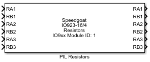
R n (n is the resistor channel number)
The requested resistance value. The number of these ports is dependent
on the channel count, which is specified by the 'Channels vector'
parameter.
-
RAn
The requested resistance between the 'CHn Terminal A' and the 'CHn
Wiper' IO pins. Only available for IO923 and IO924 potentiometer
modules.
-
RBn
The requested resistance between the 'CHn Terminal B' and the 'CHn
Wiper' IO pins. Only available for IO923 and IO924 potentiometer
modules.
The output ports are only shown when the option "Show output ports" is enabled.
Outputs
-
R n (n is the resistor channel number)
The value that the driver is trying to assign to the resistor. This
value may differ slightly from the input value and the actual value of
the resistor. The number of these ports is dependent on the channel
count, which is specified by the 'Channels vector' parameter.
-
RAn
The value that the driver is assigning to the resistor between the
'CHn Terminal A' and the 'CHn Wiper' IO pins. This value may differ
slightly from the input value and the actual value of the resistor. Only
available for IO923 and IO924 potentiometer modules.
-
RBn
The requested resistance between the 'CHn Terminal B' and the 'CHn
Wiper' IO pins. Only available for IO923 and IO924 potentiometer
modules.
Parameters
-
IO92x, IO97x module ID
If your target machine only contains one I/O module, leave the default
value (1). If more than one I/O module of this type is present, select a
unique number (1-255) for each of your modules.
-
IO92x, IO97x module type
Select the specific type of I/O module this driver block is being used
with.
-
Channel vector
This parameter allows the enabling of individual resistors channels in
any order. The parameter takes values (starting from 1) in a row vector.
The number of elements defines the number of resistors used. e.g. to use
two resistor channels enter [1, 2].
-
Initial value vector
The initial resistor impedance in Ohms. A scalar value or a vector of
the same length as the 'Channel vector' can be entered. If a scalar
value is specified, this value is applied to all resistors. For
potentiometers there are two resistors per channel, so the vector size
must be twice the size of the channel vector. The sequence is RA1, RB1,
RA2, RB2, etc. The resistors are set to their initial values between the
time the model is downloaded and the time it is started. Before the
model is downloaded, all resistors are in an "open circuit" state. To
maintain this state, use a value of 100e6 or more. Potentiometers and
High Density Resistors do not support "open circuit". They are
initialized to the highest possible resistance which they support.
-
Reset vector
The reset vector controls the behavior of the resistors at model
termination. A scalar value or a vector of the same length as the
'Channel vector' should be entered. If a scalar value is specified, this
value is applied to all resistors. If a value of 1 is entered, the
corresponding channel will be reset to the state specified in the
'Initial value vector'. If a value of 0 is entered, the channel remains
at the last state attained while the model was running.
-
Show output port(s)
Enables or disables the output port(s).
-
Sample Time
Defines the base sample time at which this driver block gets its sample hit. This
parameter can also be set to -1 for inherited
sample time. The units are in seconds.
-
PCI Slot (-1: auto-search)
There are two approaches for mapping this block to a specific I/O module installed
in your target machine. All modules of the same type must be configured using the
same method.
Auto-Search: with the default value -1 the I/O module will be automatically located in the
target machine. If you have multiple modules of the same type, you must
use explicit addressing.
Explicit Addressing: to explicitly define the logical address of the
I/O module in the target machine, you can provide the PCI bus and slot
numbers as a vector: [bus, slot]. To determine these numbers, run the
following command in the MATLAB command window:
speedgoat.getIoInterfaces("TargetName", "mySpeedgoat", "Advanced", true)Note
that the PCI address can change whenever an I/O module is added or
removed.