IO758 Usage Notes
IO758 Usage Notes — Usage information about the
I/O module
Description
This section describes how to configure the POWERLINK Controlled Node network.
XDD File
To set up POWERLINK communication, you must import the device description files of
POWERLINK controlled nodes (XDD file) into your POWERLINK managing node
configuration tool or PLC programming tool (for example, Automation Studio). Find
the XDD file of the IO758 POWERLINK Controlled Node module here:
>> [speedgoatroot, '\sg_blocks\cifx\eds\00000044_CIFX RE
                    PLS.xdd']
.
If you use warmstart parameters to simulate a POWERLINK controlled node of a
different vendor, you must import the XDD file of that particular controlled node
into your managing node configuration tool. The XDD file is generally available on
the vendor's website.
Front Plate Description
IO758 PCI and PCIe modules
The IO758 acts as one POWERLINK Controlled Node exclusively. The two RJ45
connectors simply serve to build up a line-based network structure. Plug the
cable from the POWERLINK Managing Node or the previous Controlled Node into the
first socket. Connect the second socket with the next POWERLINK Controlled Node.
The LEDs described below indicate the communication status of the single
POWERLINK Controlled Node.
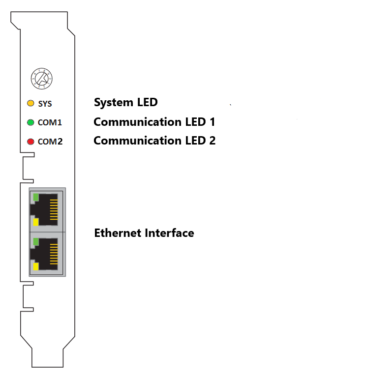
The rotary switch has no functional role.
IO758 mPCIe module
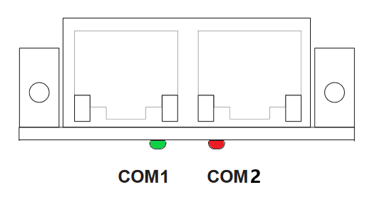
Note that in some real-time target machines,
the mPCIe module is reversed; that is, the Error LED appears on the right.
LED Status Description
Note that only the IO758 PCI and PCIe modules have the SYS LED. This LED does not
feature on the IO758 mPCIe module.