IO758 - Setup
IO758 - Setup — Configure the IO758 IO
module
Library
Simulink Real-Time - Speedgoat
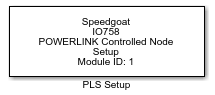
Description
Your model can contain only one Setup block
for each I/O module in your target machine.
Ports
This driver block has no input or output ports.
Parameters
Tab: Configuration
- Module ID
The Module ID has two functions:
It logically connects the Setup block and its I/O blocks
It also informs the auto-search feature of the PCI Slot parameter. If only
one I/O module of this family is installed, the Module ID must be set to
1. To see how each I/O module maps to a
Module ID, use this Speedgoat API:
speedgoat.getIoInterfaces("TargetName", "mySpeedgoat")
This Setup block belongs to two families of I/O modules that use the same hardware
for multiple protocols. Across both families, the Module ID must be unique.
IO64X/IO75X (single-node modules): IO641,
IO642, IO643, IO644, IO750, IO751, IO752, IO753, IO754, IO755, IO756,
IO758
IO64X-32/IO75X-32 (multi-node modules):
IO642-32, IO752-32, IO754-32, IO756-32
If the PCI Slot parameter is set to -1
(auto-search), the Module ID must be in the range 1:n, where 'n' cannot be larger
than the number of modules of this type installed in the target machine. Not all
installed I/O modules need to be used.
To use this Setup block with a multi-node I/O module (IO75X-32 family), the Module
ID must be defined as a two-element vector. The second vector element is the
sub-module ID. It describes the specific node (1:32) within the I/O module. The 32
nodes are internally connected to form two linear networks (daisy-chain), where the
first and the last node of both chains are externally accessible. If one node is not
configured (has no Setup block), the chain terminates at this point. The sub-module
IDs must therefore start at node 1, 16, 17 or 32 and not have any gaps.
![[Note]](images/note.png) | Note |
|---|
When using I/O modules of both families simultaneously (single-node and
multi-node I/O modules), always use explicit addressing in the PCI Slot parameter. Ignore the Module IDs returned by
the getIoInterfaces function and instead assign unique Module IDs accross all
modules used. |
-
Configuration Mode
| Note |
|---|
This parameter is obsolete and will be removed. Please always
select Warmstart. |
-
PCI Slot (-1: auto-search)
There are two approaches for mapping the block to a specific I/O
module installed in your target machine. All modules of the same
family (see Module ID above) must be configured using the same
method.
- Auto-Search: with the default value -1 the I/O module will be
automatically located in the target machine. If you have
multiple modules of the same family, the Module ID (first
vector element for a multi-node module) defines which module
is associated with this block. To see how each I/O module
maps to a Module ID, use this Speedgoat API:
speedgoat.getIoInterfaces("TargetName", "mySpeedgoat") - Explicit Addressing: to explicitly define the logical
address of the I/O module in the target machine, you can
provide the PCI bus and slot numbers as a vector: [bus,
slot]. To determine these numbers, run the following command
in the MATLAB command window:
speedgoat.getIoInterfaces("TargetName", "mySpeedgoat", "Advanced", true)Note
that the PCI address can change whenever an I/O module is
added or removed. Usually, auto-search is the best option.
Tab: Warmstart (Interface)
-
Bus startup
Communication starts
automatically
application controlled
-
Watchdog Time [ms]
Within that time the device watchdog must be retriggered from the
application program while the application program monitoring is
activated. To deactivate the application program monitoring, set
Watchdog time to 0. This function is not supported by gateway or proxy
devices.
-
I/O Status Enable
Status of the input or the output data. For each input and output data
the following status information (in Byte) is stored in the dual-port
memory:
Status 0 = None (default)
Status 1 = 1 Byte (for future use)
Status 2 = 4 Byte (for future use)
-
Disable Host Triggered Input Data Exchange
Determines whether host-triggered update for input data exchange is
enabled (checked) or disabled (unchecked).
-
Disable Host Triggered Output Data Exchange
Determines whether host-triggered update for output data exchange is
enabled (checked) or disabled (unchecked).
Tab: Warmstart (Ident)
-
Enable
If unchecked the default values are used.
-
Vendor ID
Identification number of the manufacturer Default: 0x0044
-
Serial Number
Serial number of the device Default: 0
-
Product Code
Product code of the device as specified by the manufacturer Default: 1
-
Revision Number
Revision number of the device as specified by the manufacturer
Default: 0
Tab: Warmstart (Bus)
-
Node ID (1…239)
POWERLINK Controlled Node ID Default: 2
-
DNS Node Name
DNS-compatible name of the POWERLINK Controlled Node
-
Gateway Address
Gateway address for IP stack Default: 192.168.100.254
Tab: Warmstart (Data)
-
Input Length
Length of the input data in byte Default: 4
-
Output Length
Length of the output data in byte Default: 4
-
Disable PDO Mapping Version Check
checked: PDO mapping version is checked unchecked: PDO mapping version
is not checked
-
Configure Default Objects
checked: Default objects are created (old set of previously existing
objects will be cleared) unchecked: Default objects are not created.
-
Delete Application Objects
checked: Application objects are deleted (firmware automatically does
a "Delete Application Objects") unchecked: Application objects are not
deleted