Back to Homepage
Contact Us
Customer Portal
Documentation
Solutions
Products & Services
Knowledge Center
Success Stories
Company
Documentation
CONTENTS
Speedgoat I/O Blockset
I/O Connectivity
Analog
IO17x
IO171 Pin Mapping
IO172 Pin Mapping
IO17x Usage Notes
IO17x Terminal Boxes
IO17x Setup
IO17x Analog Input
IO17x Examples
https://www.speedgoat.com/help/slrt/page/icon_documentation.jpg
v10.0.1.x
for R2026a
View other versions
IO172 Pin Mapping
IO172 Pin Mapping —
Reference information about the I/O module connector
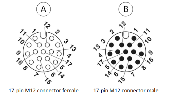
Connector A Pin Mapping
Pin
Signal
1
Analog Input 01 (+)
2
Analog Input 01 (-)
3
Excitation 01 (+)
4
Excitation 01 (-)
5
Analog Input 02 (+)
6
Analog Input 02 (-)
7
Excitation 02 (+)
8
Excitation 02 (-)
9
Analog Input 03 (+)
10
Analog Input 03 (-)
11
Excitation 03 (+)
12
Excitation 03 (-)
13
SCL (to interface a SE95 temperature sensor)
14
SDA (to interface a SE95 temperature sensor)
15
VCC +3.3 V
16
Ground
17
Ground
Connector B Pin Mapping
Pin
Signal
1
Analog Input 04 (+)
2
Analog Input 04 (-)
3
Excitation 04 (+)
4
Excitation 04 (-)
5
Analog Input 05 (+)
6
Analog Input 05 (-)
7
Excitation 05 (+)
8
Excitation 05 (-)
9
Analog Input 06 (+)
10
Analog Input 06 (-)
11
Excitation 06 (+)
12
Excitation 06 (-)
13
SCL (to interface a SE95 temperature sensor)
14
SDA (to interface a SE95 temperature sensor)
15
VCC +3.3 V
16
Ground
17
Ground
M12 Connector Pin Mapping
×
WeChat