IO135 Usage Notes
IO135 Usage Notes — Usage information about the
I/O module
DMA Setup
If DMA is enabled for analog input, analog output or both, then the model or the
asynchronous subsystem where the module is located must be triggered by the module's
interrupt.
This is required so that the sample hits of the blocks are synchronous to the
module's DMA engine.
In DMA mode, the model must contain an
Interrupt Setup block that triggers a subsystem or the model. Refer to the block
documentation for more information.
Output DMA Latency
This note shows the difference between the two configuration options for the
latency of the Analog output block in DMA mode.
The configuration is defined in the analog output tab of the Setup block.
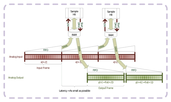
Latency as small as possible
If the latency is kept as small as possible, then the module will start to output
values immediately after receiving a frame. However, the transmission time will
vary, meaning that the delay between the sample hit of the model and the change at
the output pins is not constant. If both the analog input and output use DMA, then
the latency between measuring a value, processing and writing the value to the
output will vary.
If the DMA transfer, during one sample hit, requires more time than the previous
transfer, then the outputs will remain on the last value until the transfer has
finished.
Latency until next frame
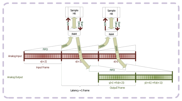
If the latency is fixed to the beginning of the next frame, then the analog
outputs will only start to output the data of the frame at the next sample hit. The
delay between the sample hit and the outputs, or between the analog inputs and the
analog outputs is therefore constant. There is no danger of running out of data at
the outputs, however, the latency will be higher.
Frame Trigger
The frame trigger starts the conversion of analog input or output data over DMA.
The advantage of operating with the frame trigger is that the data frame can be
smaller than the trigger signal and the analog input and output frames can be of
different sizes. Without the frame trigger, it is still possible to have different
sample times for the input and output, but they must complete their frames at the
same time.
The disadvantage of the frame trigger is that different conversion clocks cannot
be used for the analog input and output.
Example: Input and output frames are the same size as the
frame trigger
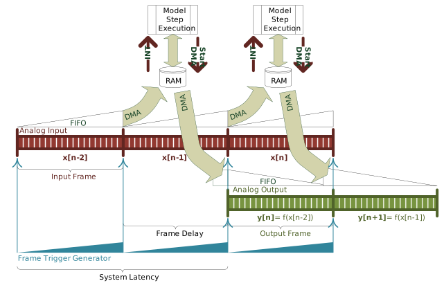
In this example, the analog input and output frames have the same size as the
frame trigger. If the analog input frame size and analog output frame size are both
100 samples/channel, then the frame trigger clock divider must be 100. This results
in a frame trigger with 100 conversions/trigger. With these settings, the IO135
module performs the analog conversions at an interval defined with the chosen
conversion clock.
When using the frame trigger, the frames are always synchronized. Consequently,
the analog input and output have to use the same conversion clock. The system
latency is therefore double the time of one frame.
Example: Input and output frames are smaller than the frame
trigger
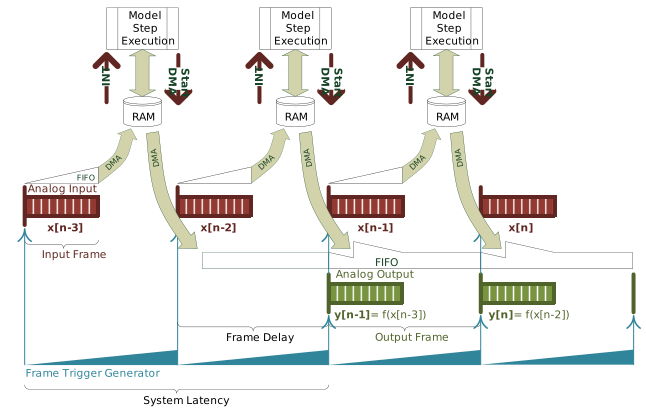
In this example, the analog input and output frames are smaller than the frame
trigger. The analog input frame size could, for example, be 40 samples/channel, the
analog output frame size could be 60 samples/channel and the frame trigger clock
divider could be 100. The result is a configuration where the system starts
converting both the analog input and output samples after a frame trigger. After 40
samples, the analog input frame is full, the ADC conversions are stopped and the
data frame is transferred over DMA to the model in Simulink. For the next 20
conversion clocks, the module will continue to update the analog outputs until the
output frame has also finished. During the last 40 conversion clocks, the module
will not perform anymore conversions. It may however load the next output frame over
DMA. The whole cycle will start again after the next frame trigger.
When using the frame trigger, the frames are always synchronized. Consequently,
the analog input and output have to use the same conversion clock. The system
latency is therefore double the time of one frame. Shorter latencies cannot be
guaranteed for every configuration.
Output Differential Signals using Single-Ended Channels
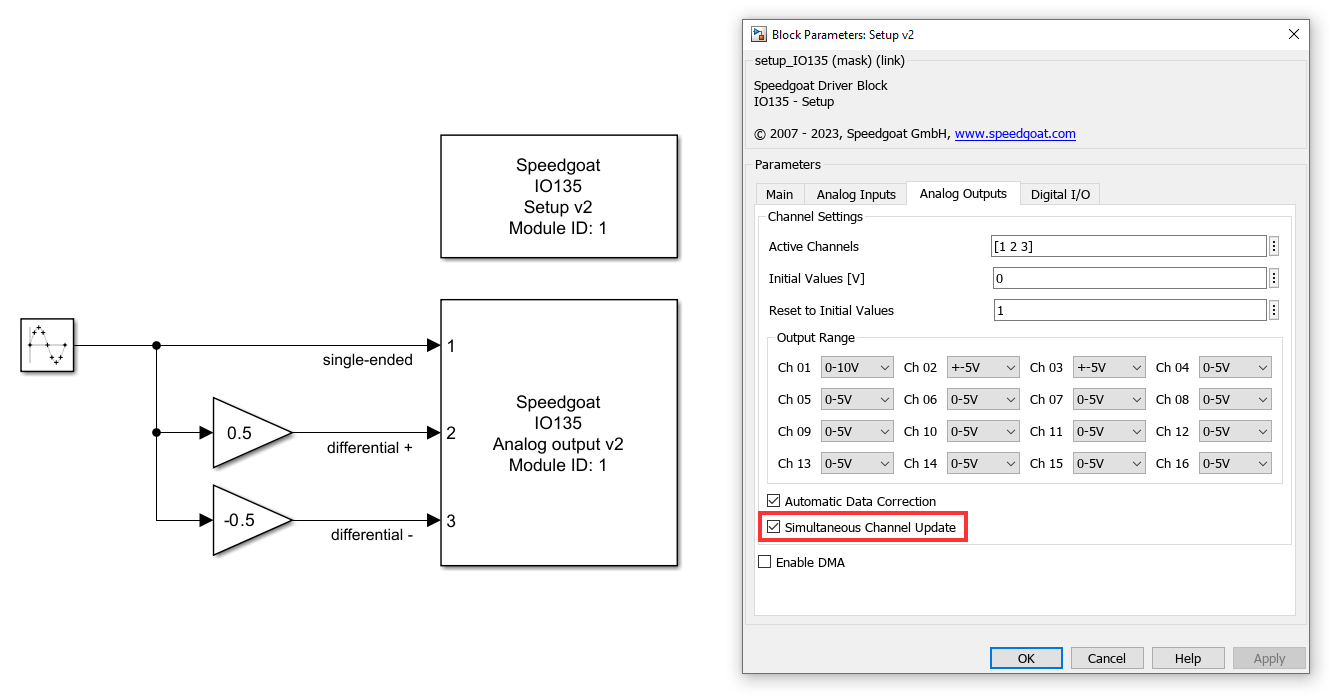
Analog I/O modules with single-ended outputs and simultaneous channel update
functionality can support differential output signals. Two single-ended channels are
needed to output one differential signal, and the Simultaneous
Channel Update setting must be enabled. The following screenshot
illustrates one way in which you can implement differential signals over
single-ended channels in Simulink. Ensure that the voltage ranges configured are
compatible with the output signals.
Manual Data Correction
Analog inputs and outputs can be calibrated manually by specifying offset- and
gain-correction values. The correction values are set per channel and voltage range
individually and are applied as follows:

The correction values are stored as two's complement 16-bit wide values in the range
–32768 to +32767. For improved accuracy, they are scaled to ¼ LSB (least
significant bit). No correction is performed for
GainCORR = 0 and
OffsetCORR = 0. Please consult the
hardware reference manual for additional information.
The calibration process is performed for an individual channel at a given voltage
range. The following steps outline a procedure to calculate
OffsetCORR and
GainCORR for an analog input channel
with an input voltage range of ±5 V. (A similar procedure can be followed for the
calibration of other voltage ranges or analog output channels).
Disable data correction
Set the data correction method in the Simulink block to None
Estimate OffsetCORR
Supply a 0 V-certified reference voltage to the input channel and
record the reading
Use the reading
(OffsetMEASURE) to
calculate OffsetCORR
Offset_CORR = Offset_MEAS/(LSB/4);
(LSB denotes least significant bit and equates to LSB = full scale
range/adc resolution. Please consult the hardware reference manual for
additional information.)
Estimate GainCORR
Sequentially supply -5 V and 5 V (certified reference
voltage) to the input channel and record the readings
Use the readings (-5 V: voltage_m5,
5 V: voltage_p5) to calculate
GainCORR
voltageRange_target = +5 -(-5); % -> 10 V
voltageRange_measurement = voltage_p5 - voltage_m5;
Gain_CORR = (voltageRange_target - voltageRange_measurement)/(LSB/4);
Verify the manual data correction
In the Simulink block, set the data correction method to Manual and input
OffsetCORR and
GainCORR
Supply some sample voltages and verify the readings. Make fine
adjustments as needed
Inter-Module Synchronization Setup
With the help of inter-module synchronization, the IO132-IO135 range of modules allows
for synchronous DMA usage of more than one module. Some of the possible use cases are
listed below.
Conversion Signals
To use inter-module synchronization, the conversion signals must meet certain timing
and voltage requirements. The requirements are listed below. Note that when inter-module
synchronization is used with a module from the IO132-IO135 range, these requirements are
taken care of automatically.
Conversion Clock
The conversion clock signal is an active-high pulse signal that determines the basic
frequency of the data output or the acquisition of the modules.
Frame Trigger
The frame trigger signal is a divider of the conversion clock signal. It indicates the
time when the DMA shifts the data in the desired direction. The first falling edge of
the frame trigger also makes up the starting interrupt signal of the module.
Conversion Signal Requirements
The exact timing requirements for the inter-module synchronization are as
follows:
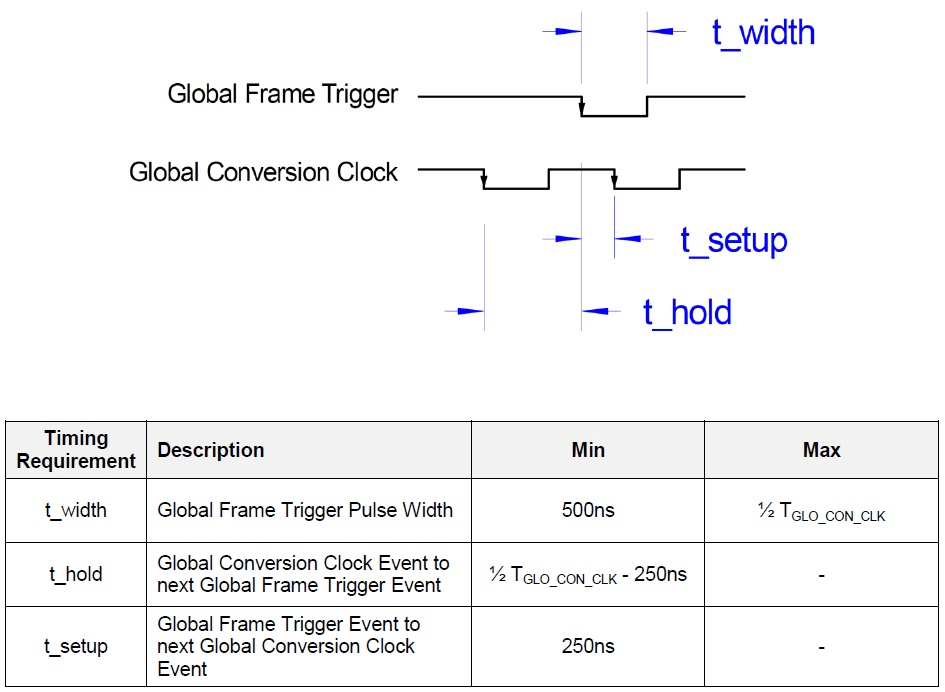
Here is an example for the conversion signals exchanged between two IO132-IO135 I/O
modules. The red signal is the conversion clock signal, the signal in blue is the frame
trigger signal. The frame trigger clock divider is set to 10.

Hardware Setup
Front I/O:
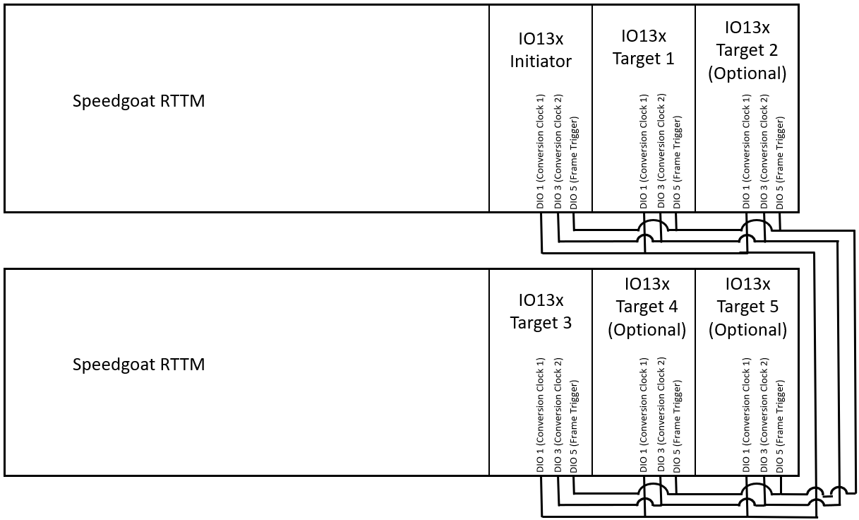
When using inter-module synchronization in Front I/O mode, connect all the
concerned modules' DIO 1, DIO 3 and DIO 5 lines. In a case where only one
conversion clock is used, the other conversion clock line can be omitted.
However, the respective DIO line cannot be used for its original purpose.
Rear I/O:
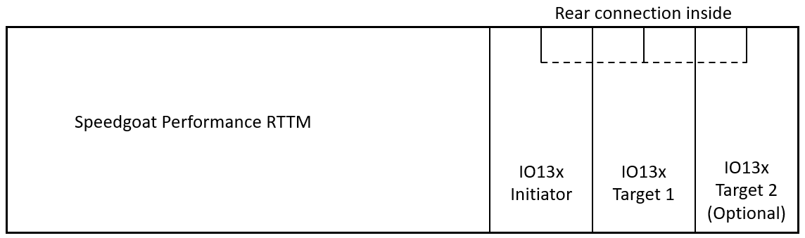
If all dedicated modules are to be connected via rear I/O connection, the DIO
ports can all be used for their intended purpose. If you wish to upgrade your
system to support rear I/O configuration, please contact Speedgoat to check
whether your system supports rear I/O configuration.
Software Setup
Initiator and Target Modules in the Same Real-Time
Target Machine
When both the initiator module and a target module(s) are installed in the
same machine, inter-module synchronization must be activated to use DMA on all
modules.
Initiator and Target Modules in Separate Real-Time
Target Machines
Another use case for inter-module synchronization is the synchronous start of
several real-time target machines. For this purpose, we need to set the relevant
module on every target machine as model trigger. We then need to start the
real-time target machine containing the target module first. The application
will transition to the “running” state, without the model execution starting.
This only happens when the machine gets the Frame Trigger signal from the
real-time target machine containing the initiator module. All connected modules
will then start to sample and output synchronously, on different
machines.
PWM Signal from an External Source or a Speedgoat
Configurable I/O Module as Synchronization Signal
If the aforementioned conversion signal requirements are met, an external
source or another module present inside or outside the dedicated real-time
target machine can be used to trigger the IO132-IO135 modules set to target
mode. Note that the exact bus/slot number must be specified at every instance to
use the IO132-IO135 as interrupt trigger of your model or subsystem.