IO108 - Analog output (DMA)
IO108 - Analog output (DMA) —
Writes the IO108 analog outputs (DMA)
Library
Simulink Real-Time - Speedgoat
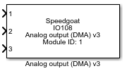
Description
This driver block can be used to output frame-based data. A Setup block is not
required when using the DMA output block.
This I/O module has 3 function modes:
Asynchronous data output (replay function): frame-based data is/are
replayed to the output. No external clocking needed. The model must be
driven by the IO108 I/O module interrupt.
Synchronized with a IO107/IO108 module: the module must be externally
clocked by a IO107/IO108 I/O module and the model must be driven by the
initiator IO107/IO108 I/O module interrupt.
Synchronized with the IO109 I/O module: the module must be externally
clocked by the IO109 I/O module and the model must be driven by the
IO109 I/O module interrupt.
In DMA mode, the model must contain an
Interrupt Setup block that triggers a subsystem or the model. Refer to the block
documentation for more information.
Ports
This block has one input port per output channel. The width of the input is equal
to the frame size and each element of this vector is one sample.
Inputs
-
X (X is the analog channel number)
The value to be output from analog channel X in volts.
Data Type:
double
Parameters
All the configuration settings of the IO108 I/O module in DMA mode can be found in
the two tabs of the DMA output parameter dialog.
Main Tab
-
Module ID (IO107/IO108)
A unique module ID must be used for each type of I/O module Setup
block in your model.
The module ID has two functions:
It defines the logical connection to link the I/O module
driver blocks with each other
It also has an impact on the PCI slot auto-search feature:
if only one I/O module is installed, the module ID must be
set to 1. If multiple modules are installed, it must be in
the range 1:n. Not all the I/O modules installed in the
target machine need to be used
The IO107 I/O module uses the same module identifiers as the IO108 I/O
module. If your target machine contains both of these modules, assign
different values to each of them.
-
PCI Slot (-1: auto-search)
There are two approaches for mapping this block to a specific I/O module installed
in your target machine. All modules of the same type must be configured using the
same method.
Auto-Search: with the default value -1 the I/O module will be automatically located in the
target machine. If you have multiple modules of the same kind, the
Module ID defines which module is associated with this block. To see how
each I/O module maps to a Module ID, use this Speedgoat API:
speedgoat.getIoInterfaces("TargetName", "mySpeedgoat")
Explicit Addressing: to explicitly define the logical address of the
I/O module in the target machine, you can provide the PCI bus and slot
numbers as a vector: [bus, slot]. To determine these numbers, run the
following command in the MATLAB command window:
speedgoat.getIoInterfaces("TargetName", "mySpeedgoat", "Advanced", true)Note
that the PCI address can change whenever an I/O module is added or
removed – usually, auto-search is the best option.
-
Auto-Calibration at Download
The auto-calibration is enabled by default to obtain maximum
measurement accuracy. The auto-calibration function compensates for
component aging, and minimizes the effects of temperature on accuracy.
The calibration normally takes approximately two seconds, so we
recommend increasing the host-target communication time-out in the model
configuration parameters by the same amount of time. The calibration is
not re-executed during normal start/stop operation once the target
application has been downloaded.
Warning: During the calibration
process various signals may be present at the output pins. These signals
will not exceed the configured voltage range.
-
Enable Remote Ground-Sensing
Enable remote ground-sensing to compensate for a ground potential
difference in single-ended mode between the ground connection at the
load and the output return pin. "REM GND SENSE" must be connected to the
remote system ground.
-
Synchronization Mode
Set the working mode of the I/O module:
Select "Async (replay function)" to replay data to the
output without any external I/O module.
Select "Sync to IO107/IO108 (external DAC trigger source)"
to trigger this module using an external DAC signal provided
by another IO107/IO108 board. Connect "CLOCK I/O" to "DAC
CLK OUT".
Select "Sync to IO109 (external clock source)" to
synchronize the module with the IO109 I/O module analog
input (for example, for a Simulink Real-Time audio system
model). Connect "CLOCK I/O" to "EXT CLK OUT".
-
External Sync Signal Type
Select either LVDS or TTL mode for the sync I/Os. In TTL mode, use
only the (+) pins. In addition, the (-) pins should be grounded to
digital return.
-
Frame Size, Sample Rate and Block Sample Time
Parameter dependency is as follows: frame size = block sample time ×
sample rate. By defining two parameters, an equation will determine the
third parameter automatically, provided the parameter value for the
third parameter is set to -1.
For example: We select a frame size of 32 and a sample rate of
44,100 Hz and specify the block sample time as -1. The block sample
time is automatically computed to be 725.6 µs. In other words, this
model would execute every 725.6 µs, which is every 32 samples at
44.1 kHz.
-
Frame Size
The number of samples per frame. An interrupt occurs each time the I/O
module acquires a frame. In Async (replay function) mode, the minimum
frame size is 5. Refer to the "Frame Size, Sample Rate and Block Sample
Time" section for more information.
-
Sample Rate
The frequency at which the samples are taken. This parameter is in
Hertz, and must be between 172 and 450,000 Hz (172 Hz to
450 kHz). Refer to the "Frame Size, Sample Rate and Block Sample
Time" section for more information.
-
Block Sample Time
The time between frame completions. Note: The block sample time can
only be a multiple of 1/sample rate. Refer to the "Frame Size, Sample
Rate and Block Sample Time" section for more information.
Analog Output Tab
-
Active Channels
Select the active output channels in a vector. The IO108 I/O module
supports eight channels. The order inside the vector defines the input
port order of the Analog output block.
Examples:
Change order: "[2 1 4 3]"
Simply use all the channels in ascending order:
"1:8"
Only use channels 2 and 3: "[2 3]"
-
Output Range
The voltage range for all analog output channels. This driver does not
allow different ranges for individual channels. The following voltage
ranges are available: ±1.25 V, ±2.5 V, ±5 V,
±10 V
-
Initial values
This parameter is only available in Async mode.
Define the initial voltage level on the analog outputs after the model
is downloaded and after the model is stopped. The voltages can be set
individually by entering a vector which maps to the active channels'
vector. A scalar value applies to all active channels.
Examples: