Interrupt - CoS v2
Interrupt - CoS v2 — The CoS (Change of State)
interrupt block is used to set up an interrupt event on an input of a
configurable I/O module that triggers the Simulink model. Interrupts can also be
generated internally with a configurable frequency.
Library
Simulink Real-Time - Speedgoat
Description
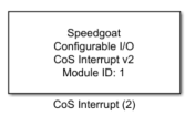
The CoS interrupt block is used to set up an interrupt event on an input of a
configurable I/O module that triggers the Simulink model. Advanced settings enable
the input signal to be debounced and events to be delayed. A threshold can also be
inserted to skip events or repeat an event multiple times. Interrupts can also be
generated internally on the FPGA with a configurable frequency.
Ports
Depending on which output ports are enabled in the dialog fields of the CoS
interrupt driver block, this driver block has up to 2 output ports and contains no
input ports. The number of selected outputs can influence the performance of the CoS
interrupt driver block. Please refer to Interrupt Usage Notes -
Latency
The available output ports are:
Outputs
-
Flag
This double-type output has the same width as the "Channel vector
parameter", where each element returns the number of missed interrupts.
A missed interrupt is only detected when repetitions are created. This
port is only active when the "Show missed interrupt output" option is
checked.
-
Timestamp
This double-type output has the same width as the "Channel vector
parameter", where each element returns the timestamp of the last
interrupt received. This port is only active when the "Show timestamp
output" option is checked.
Parameters
Tab: Module setup
-
Configurable I/O Module ID
This parameter associates a code module block with a configurable I/O module setup
block. Set this value to match the Module ID defined in the setup block of the
required configurable I/O module.
-
Channel Vector
A vector of channels this driver block entity will access. You can specify
channels in the range 1-N (N = the number of channels implemented in your specific
configuration file defined in the Setup block). The width of this vector also
defines the subsequent size of some of the following parameters if scalar expansion
applies. With a single block, all the channels of the block are synchronized.
-
Sample Time
Defines the base sample time at which this driver block gets its sample hit. This
parameter can also be set to -1 for inherited
sample time. The units are in seconds.
- Interrupt source
Defines the source for interrupts. There are two possibilities:
When "FPGA input pin" is selected, there are multiple
settings available to adjust the behavior of the interrupt input.
When "internally generated" is selected, the only
setting available is the Interrupt frequency
- Edge detection
This setting defines whether the rising edge (value 0), the falling
edge (value 1) or both transitions (value 2) of the input signal are
recognized as events.
-
Debounce duration vector
A vector* of debounce durations in seconds. Defines the debouncing
time. After the first registered transition, all following transitions
will be ignored, until the debounce duration is reached. To turn off
debouncing, enter the value 0. Range: from 0 to 57 seconds.
-
Interrupt delay vector
A vector* of delay values in seconds. Defines the time that the
debounced signal is delayed before the interrupt is asserted. During the
delay, new interrupts are ignored, but the flag counter is incremented.
To turn off the delay, enter the value 0. Range: from 0 to 57 seconds.
-
Advanced settings
This checkbox enables the advanced settings for the interrupt input. A
threshold or a number of repetitions can be defined.
-
Threshold vector
A vector* of interrupt event thresholds. Defines the number of
interrupts to reach, before one interrupt is propagated. The threshold
operation is executed after the delay and before the generation of
repetitions. To turn off the threshold, enter the value 0. This
parameter is only visible when Advanced settings are enabled.
-
Repetition vector
A vector* of interrupt repetitions. Defines the number of repetitions
for one interrupt. The time between the repetitions is defined in the
"Time gap vector" -dialog field. During the repetitions, new interrupts
are ignored, but the flag counter is incremented. The repetitions are
generated after the threshold operation. To turn off repetitions, enter
the value 0. This parameter is only visible when Advanced settings are
enabled.
-
Time gap vector
A vector* of time between the repetitions. Defines the time gap
between the repetitions. Range: from 13.3ns to 57 seconds. This
parameter is only visible when Advanced settings are enabled.
-
Interrupt frequency
A vector* of frequencies. Defines the frequency of occurring
interrupts. The smallest step width depends on the FPGA frequency; for
example, when the FPGA frequency is 75MHz, the smallest change between
two period times is 13.3ns. The precise computed time in seconds appears
next to the Interrupt frequency parameter. This parameter is only
visible when the interrupt source is "internally generated".
![[Note]](images/note.png) | Note |
|---|
The width of the vector must be equal to the width of the Channel vector
parameter. Alternatively, if a scalar value is specified, its value will be used
for all channels. |
Tab: Output port settings
-
Show timestamp output
Enables the timestamp output port to read the timestamp of the latest
interrupt. The timestamp is a 64-bit counter value on the FPGA which
starts to count when the model is started.
-
Show missed interrupt output
Enables the Flag output port to read the number of missed interrupts.