IO397-50k - Setup
IO397-50k - Setup — Setup the IO397-50k configurable I/O module
Library
Library: Speedgoat
Description
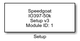
Use the Setup block to define the functionality of this I/O module by selecting a
configuration file. You can also use this block to configure all the digital I/O pins
(pull resistors, I/O voltage, termination, etc.) of this configurable I/O module.
Your model must contain a Setup block for every configurable I/O module you intend to
use.
Ports
This driver block has no input or output ports.
Parameters
Module setup Tab
-
Hardware
Select the name of the configurable I/O module for which you are defining the
setup parameters.
-
Configurable I/O Module ID
The Module ID identifies the configurable I/O
module in the target machine and creates a logical connection to all the code module
blocks associated with this I/O module. The Module
ID of all the code module blocks intended for use with a specific I/O
module in your machine must match the Module ID in
the IO3xx Setup block.
Unlike other module types, the Module ID
parameter must be unique for each Simulink-programmable and configurable I/O module.
To obtain the Module ID for use with your I/O
modules, run the following Speedgoat API in the MATLAB command window:
>> speedgoat.getIoInterfaces

                Slot            IO_Interface          ModuleID
                _________    _______________________    ________

                Host Link    Onboard Ethernet (I219)       -
                IO731_1      IO731 (I210)                  1
                2            IO336-325k                    3
                3            IO334-325k                    4
                4            IO334-325k                    1
5 IO344-930k-27DR 2![[Important]](images/important.png) | Important |
|---|
If your target machine contains more than one configurable or
Simulink-programmable I/O module of the same type (e.g. 2x IO334-325k), but the
model does not contain IO3xx Setup blocks for all of these modules, use explicit
addressing for the PCI Slot parameter to
clarify the module you want to use. |
Example Setup for a Target Machine with the I/O Modules
Listed Above:
To run a model with PWM Generation on the IO336-325k in slot 2 and PWM Capture on
the IO334-325k in slot 3, configure two IO3xx Setup blocks: one with ModuleID=3 for
the IO336, and one with ModuleID=4 for the IO334. As there are two IO334 I/O modules
in the machine, use explicit addressing for the PCI
Slot parameter. Finally, set the ModuleIDs of the PWM blocks:
configure the PWM Generation block with ModuleID=3 and the PWM Capture block with
ModuleID=4.
-
PCI Slot (-1: auto-search)
There are two approaches for mapping this block to a specific I/O module installed
in your target machine. All modules of the same type must be configured using the
same method.
Auto-Search: with the default value -1 the I/O module will be automatically located in the
target machine. If you have multiple modules of the same type, you must
use explicit addressing.
Explicit Addressing: to explicitly define the logical address of the
I/O module in the target machine, you can provide the PCI bus and slot
numbers as a vector: [bus, slot]. To determine these numbers, run the
following command in the MATLAB command window:
speedgoat.getIoInterfaces("TargetName", "mySpeedgoat", "Advanced", true)Note
that the PCI address can change whenever an I/O module is added or
removed.
-
Configuration File (Bitstream)
This parameter defines the configuration file (bitstream) to download to the FPGA
of your configurable I/O module when your Simulink model is built and the
application deployed to the target machine. The configuration file defines the pin
mapping and the implemented functionality (code modules). The dropdown will show
installed configuration files, files located in the actual working directory and
files from installed Speedgoat I/O Configuration Packages. A configuration file can
also be selected from a different location by using the Browse button. The entries are automatically limited to
configuration files matching the selected I/O module.
- Browse...
This button opens a file explorer window to select a configuration file
(.mat-file) from any location. The selected file is automatically applied as the new
configuration file if compatible with the selected I/O module.
![[Note]](images/note.png) | Note |
|---|
| Moving or renaming the file will remove the file from the dropdown, since the
Setup block cannot find the file anymore. |
- Configuration File Information
This collapsible panel shows additional information about the selected
configuration file.
- Timestamp
This field shows the timestamp information of the configuration file
in the format dd/MM/YY hh:mm:ss.
- Revision
This field shows the revision of the selected configuration file. By
default, the revision is "1.0" and increases when there are updates to
the configuration file.
- FPGA Frequency
This field shows the FPGA base clock for the selected configuration
file. The FPGA frequency defines the base rate of the implemented
functionality from a configuration file. It therefore has a direct
influence on the applicable rates in code modules.
- Tick time
This field shows the corresponding time of one FPGA tick for the
selected configuration file. For some code modules this value is used to
calculate time-related parameters.
- Pin Mapping
This button opens a window with the implemented pin mapping for the
currently selected configuration file. The button is only visible, if
the image is included in the selected configuration file.
IO3xx Pull Resistor Tab
This tab allows you to define the pull resistor settings for the front I/O
lines.
- Settings per Port
- Pull Resistors
Select the pull resistor of the digital TTL I/O lines of the
corresponding port.