Analog IO397 - Input v1
Analog IO397 - Input v1 — This driver block is
available for the IO397-50k module only.
Library
Simulink Real-Time - Speedgoat
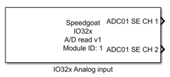
Description
This driver block is available for the IO397-50k module only.
Your model can only contain one of these blocks for each I/O module in your target
machine.
Ports
This block has as many outputs as defined by the channel vector.
Outputs
-
X (X is channel number)
The value read from analog input X. Type double.
Parameters
-
Configurable I/O Module ID
This parameter associates a code module block with a configurable I/O module setup
block. Set this value to match the Module ID defined in the setup block of the
required configurable I/O module.
-
Channel Vector
A vector of channels this driver block entity will access. You can specify
channels in the range 1-N (N = the number of channels implemented in your specific
configuration file defined in the Setup block). The width of this vector also
defines the subsequent size of some of the following parameters if scalar expansion
applies. With a single block, all the channels of the block are synchronized.
-
Analog input range
For better accuracy, select the input voltage range - this parameter
is used to indicate the expected input voltage range:
5.12 [V]
± 5 [V]
± 5.12 [V]
10[V]
10.24[V]
± 10 [V]
± 10.24 [V]
-
Analog Input Trigger - ADC Sample Trigger
The block supports four trigger options for the analog inputs:
Model Step At each model
sample step the analog input channels are triggered and the
driver reads the analog data from the previous sample
step.
I/O Module Clock The
triggering of the analog channels is based on internal
clocking functionality. The sample frequency can be set in
the ADC Sample Rate
parameter. If the ADC Sample Rate is set to 0, the maximum
achievable rate will be set.
I/O Module Internal
Signal The triggering of the analog channels
is based on I/O module internal signals. The available
signals can be selected in the Internal Signal dropdown and depend on what
is supported in the corresponding configuration file.
I/O Module Digital I/O
The triggering of the analog channels is based on a
configurable digital I/O pin. Both input and output signals
are possible to use for triggering.
Note: the available trigger options depend on the
implementation of your specific configuration file.
-
Sample Time
Defines the base sample time at which this driver block gets its sample hit. This
parameter can also be set to -1 for inherited
sample time. The units are in seconds.