Pulse Counter v1
Pulse Counter v1 — The Pulse Counter block
configures pulse counting functionality for an input signal in a configurable
I/O module
Library
Simulink Real-Time - Speedgoat
Description
The pulse counter is a signed 31-bit counter which can be configured to count
rising, falling, or both edges of a pulse signal in either an increasing or
decreasing direction.
Ports
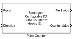
This driver block has two input and two output ports:
Inputs
-
Reset
Resets the counter value of all channels to 0.
This port can be disabled in the Input and Output Configuration
tab.
-
Direction
Defines the counting direction of the individual channels.
0: Decreasing
1: Increasing
This port can be disabled in the Input and Output Configuration tab.
If disabled, the count direction can be set on the Pulse Counter tab
with the Direction Source and Direction parameters.
Outputs
-
Pin Status
Debounced value of the pulse input signal.
This signal allows the pulse input to be used as a standard digital
input in addition to the pulse counting functionality. As with other
digital inputs, changes in the digital input signal with a duration less
than the driver block sample time may not be propagated to the driver
block output. However, these changes will still be detected by the pulse
counter.
-
Counter Value
Current value of the signed 31-bit counter.
The counter is free-running and will overflow at its minimum (-2^30)
or maximum (2^30-1) value.
Parameters
Tab: Module Setup
-
Configurable I/O Module ID
This parameter associates a code module block with a configurable I/O module setup
block. Set this value to match the Module ID defined in the setup block of the
required configurable I/O module.
-
Channel Vector
A vector of channels this driver block entity will access. You can specify
channels in the range 1-N (N = the number of channels implemented in your specific
configuration file defined in the Setup block). The width of this vector also
defines the subsequent size of some of the following parameters if scalar expansion
applies. With a single block, all the channels of the block are synchronized.
-
Sample Time
Defines the base sample time at which this driver block gets its sample hit. This
parameter can also be set to -1 for inherited
sample time. The units are in seconds.
Tab: Pulse Counter
-
Operating Mode
Defines the operating mode of the counter.
Rising Edge (Default):
Count rising edges of pulse input.
Falling Edge: Count
falling edges of pulse input.
Rising + Falling Edge:
Count both rising and falling edges of pulse input.
If Channel Configuration is set to Individual Channels, this parameter
is replaced with the parameters Rising Edge Channels, Falling Edge
Channels, and Rising + Falling Edge Channels.
-
Channel Configuration
Defines how channel operating mode and direction configuration is
applied.
All Channels (Default):
Operating Mode and Direction (if Direction input is
disabled) are applied to all enabled channels.
Individual Channels:
Operating Mode and Direction can be set for each channel
independently.
-
Direction Source
Defines the source of the counter direction. Only available when
Direction input is disabled on the Input and Output Configuration
tab.
To set the Direction Source on a per-channel basis, create one Pulse
Counter for the channels with source Model and one for the channels with
source External Signal.
-
Direction
Defines counting direction. Only available when the Direction input
port is disabled and the Direction Source is set to Model.
-
Debounce Duration [s]
Defines the time in seconds during which the pulse counter input
signal must be stable before an edge is detected. Defaults to 100e-9
(100 ns).
The range and resolution of the debounce duration depend on the module
frequency configured in the Setup block. The Effective Debounce Duration therefore indicates the
applied duration at the module level.
To disable debouncing, enter the value 0.
The debounce vector sets the debounce time for the capture inputs.
Correct values are in the range 0 to 2^8-1 ticks (e.g. 3.413
microseconds at a frequency of 75 MHz). The parameter must be a scalar
value which applies to all channels defined in the Channel Vector
Tab: Input and Output Port Configuration
-
Show Reset
Enables the Reset input port. Enabled by default.
-
Show Direction
Enables the Direction input port. Enabled by default.
If this port is disabled, the count direction can be set on the Pulse
Counter tab with the Direction Source and Direction parameters.
-
Show Pin Status
Enables the Pin Status output port. Enabled by default.
-
Show Counter Value
Enables the Counter Value output port. Enabled by default.