IO974, IO975 - Thermocouple simulation
IO974, IO975 - Thermocouple simulation — Writes the
IO974 and IO975 voltage outputs
Library
Simulink Real-Time - Speedgoat
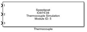
Description
Your model can only contain one of these blocks for each I/O module in your target
machine.
Ports
Inputs
-
X (X is the thermocouple channel number)
The value to be output from thermocouple channel X in millivolts. Type
double.
The voltage provided at Vo is relative to Vcold. This allows the
channel to compensate for the presence of small voltages at the Vcold
input.
Parameters
- Module ID
If your target machine only contains one I/O module, leave the default
value (1). If more than one I/O module of this type is present, select a
unique number (1-255) for each of your modules.
-
Module type
Select the type of I/O module with which this driver block will be
used.
-
Active Channels
Select the active input/output channels in a vector. A defined number of channels
can be selected using square brackets, for example [1 2 3]. A sequence of channels
can be selected using a colon, for example, 1:4.
-
Initial Values
Define the initial signal level present on the outputs after the application has
been downloaded. The values can be set individually by entering a vector: the value
at a certain position in the Initial Values vector is applied to the channel as
defined in the Active Channels vector. A scalar value applies to all the channels;
for example, for individual values, type "[1 1.5 0 2.5]", and to set all channels to
zero, type "0".
-
Reset to Initial Values
Define whether the initial values are also applied once the application has
stopped. The behavior can be set individually for each channel using a vector. A
scalar value applies to all the channels; for example, for individual values, type
"[1 0 0 1]", and to set all channels to zero, type "0". "1" means use the Initial
Value and "0" means keep the latest value.
-
Range
Select the voltage range for the output channels: auto (max. ±100mV),
±20mV, ±50mV or ±100mV. Auto range automatically switches between the
three ranges according to the requested voltage in order to provide the
finest voltage resolution and best accuracy available. At the changeover
point between each range there may be small discontinuities in the
output voltage steps. The range can be set individually for a group of
channels depending on the total amount of available channels.
-
Enable Remote Sense (IO974 only)
Enable remote sense to compensate for a ground potential difference
between the front panel ground (Pin78) and the remote ground.
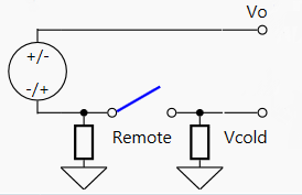
The module uses the Vcold input as a reference to the front panel
ground during initialization to check for a connection. If Vcold is left
unconnected but remote sense is still enabled, the I/O module uses the
front panel ground (Pin78) as a reference instead of the Vcold input.
The possible combinations are as follows:
-
Sample Time
Defines the base sample time at which this driver block gets its sample hit. This
parameter can also be set to -1 for inherited
sample time. The units are in seconds.
-
PCI Slot (-1: auto-search)
There are two approaches for mapping this block to a specific I/O module installed
in your target machine. All modules of the same type must be configured using the
same method.
Auto-Search: with the default value -1 the I/O module will be automatically located in the
target machine. If you have multiple modules of the same type, you must
use explicit addressing.
Explicit Addressing: to explicitly define the logical address of the
I/O module in the target machine, you can provide the PCI bus and slot
numbers as a vector: [bus, slot]. To determine these numbers, run the
following command in the MATLAB command window:
speedgoat.getIoInterfaces("TargetName", "mySpeedgoat", "Advanced", true)Note
that the PCI address can change whenever an I/O module is added or
removed.