IO821 Pin Mapping
IO821 Pin Mapping — Reference information about
the I/O module connector
Description
The IO821 provides a 25-Pin TIMING connector and an optional coaxial input for
the GNSS antenna (IO821-GNSS only).
When the IO821 is used for generating interrupts to trigger the model, the
External HW Sync Output produces a 5 V square wave where the rising edge
internally produces the interrupt. This square wave can be used to synchronize
external systems to the model sample rate.
Adapter Cable
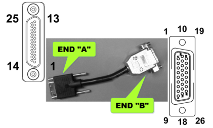
The adapter cable is used to connect the micro 25-pin timing interface connector
on the card to the breakout cable. It is wired 1 to 1.
Breakout Cable
The breakout cable is used to split the pins of the interface connector to
different connectors grouped by functionality.
The basic breakout cable does not make all the functionality of the interface
connector available.
Refer to the "Premium Breakout Cable" section below.
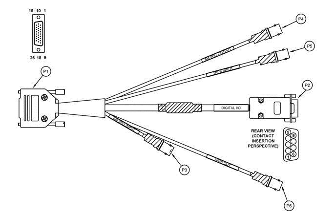
The breakout cable provides convenient coaxial and DSUB9 connectors.
P2 - DIGITAL I/O (DB-9 FEMALE)
P3 - IRIG AM INPUT (BNC FEMALE)
P4 - IRIG AM OUTPUT (BNC FEMALE)
P5 - 1PPS INPUT (BNC FEMALE)
P6 - 1PPS OUTPUT (BNC FEMALE)
Premium Breakout Cable
The premium breakout cable provides more connectors, especially two additional
DSUB9 connectors and a 10 MHz Sine Wave output.
By default, the premium breakout cable is not contained in the IO821 package.
Contact Speedgoat to order the cable.
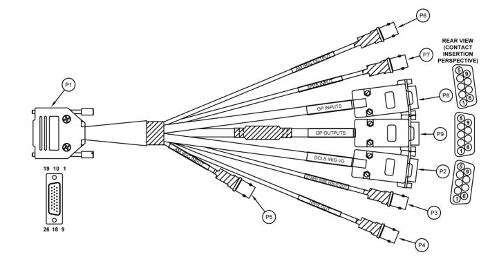
P2 - IRIG DCLS I/O (DB-9 FEMALE)
P3 - 10 MHz SINE WAVE OUTPUT (BNC FEMALE)
P4 - 1PPS OUTPUT (BNC FEMALE)
P5 - IRIG AM INPUT (BNC FEMALE)
P6 - IRIG AM OUTPUT (BNC FEMALE)
P7 - 1 PPS INPUT (BNC FEMALE)
P8 - GP INPUT (DB-9 FEMALE)
P9 - GP OUTPUT (DB-9 FEMALE)