IO755 Usage Notes
IO755 Usage Notes — Usage information about the
I/O module
Description
This section describes how to configure the EtherNet/IP network.
I/O Module configuration with SYCON.net
During initialization of the real-time application, the block reads two
configuration files from the hard drive of the target machine and configures the
EtherNet/IP Scanner protocol stack. Use the SYCON.net configuration tool to create
such files.
![[Tip]](images/tip.png) | Tip |
|---|
Download the SYCON.net configuration tool from the Speedgoat Customer Portal. Login to
your Speedgoat account. In the Downloads section, navigate to Software and click
SYCON.net (v1.500 Build 231214). |
In addition to this short introduction, please read the SYCON.net help
documentation for detailed information about how to set up an EtherNet/IP network and
export the module configuration file.
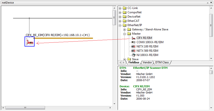
Open SYCON.net and locate the "CIFX RE/EIM" device. Drag and drop the
device to the main panel.
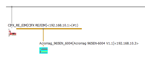
From the lists Stand-Alone Slave and Slave you can select Ethernet/IP
adapters to add to the EtherNet/IP network. Simply drag and drop the
devices.
![[Note]](images/note.png) | Note |
|---|
You can add EDS files of others devices by following Network, Import
Device Description. |
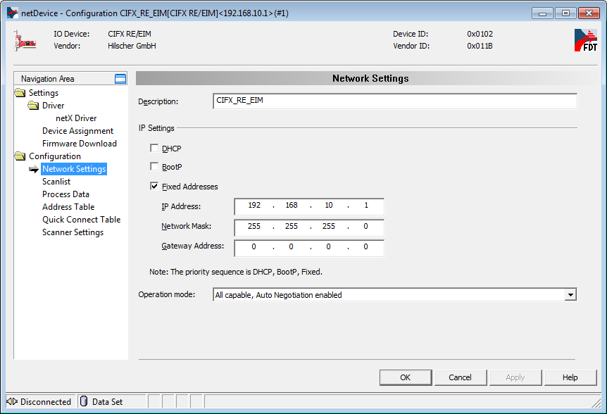
Double-click on the icon to open the Configuration window.
Navigate to Configuration, Network Settings. You can select all available
options.
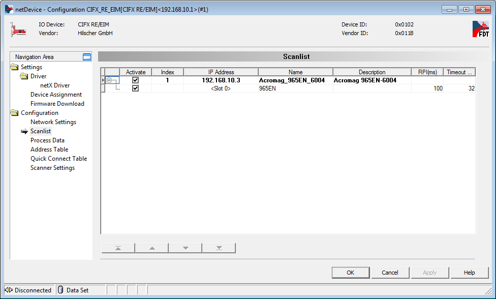
Navigate to Configuration, Scanlist. For each connected device you can
modify the IP address, the Requested Packet Interval (RPI, in ms), and the
timeout.
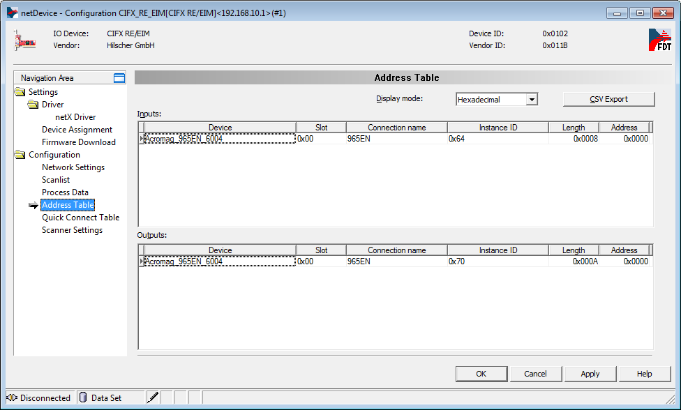
Navigate to Configuration, Address Table. Note the Length and Address
information that you will need when configuring the Simulink driver
blocks.
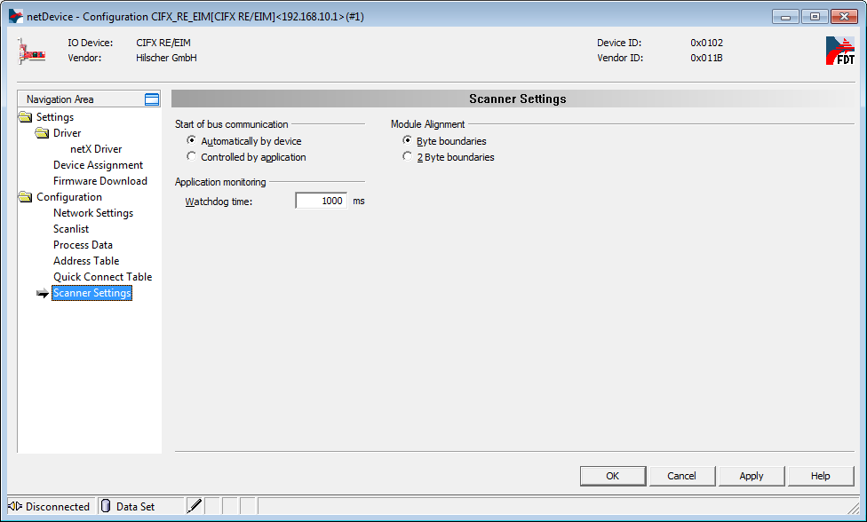
Navigate to Configuration, Scanner Settings.
Apply the configuration and close the windows. Right click on the Scanner
icon and select Additional Functions, Export, DBM/nxd.
Select a name for the file, e.g.: scanner.nxd. Save the file in your
current MATLAB workspace.
| Note |
|---|
This operation will generate two files: |
scanner.nxd
scanner_nwid.nxd
Enter the paths to the files in the Configuration File parameters of the Setup block. Specify the input and output port lengths in the Send and Receive blocks according to the configuration defined in
SYCON.net.
Front Plate Description
IO755 PCI and PCIe modules
The IO755 acts as one EtherNet/IP Scanner exclusively. The two RJ45
connectors simply serve to build up a line-based network structure. Plug the
cable from the previous EtherNet/IP Adpater into the first socket. Connect the
second socket with the next EtherNet/IP Adapter. The LEDs described below
indicate the communication status of the single EtherNet/IP Scanner.
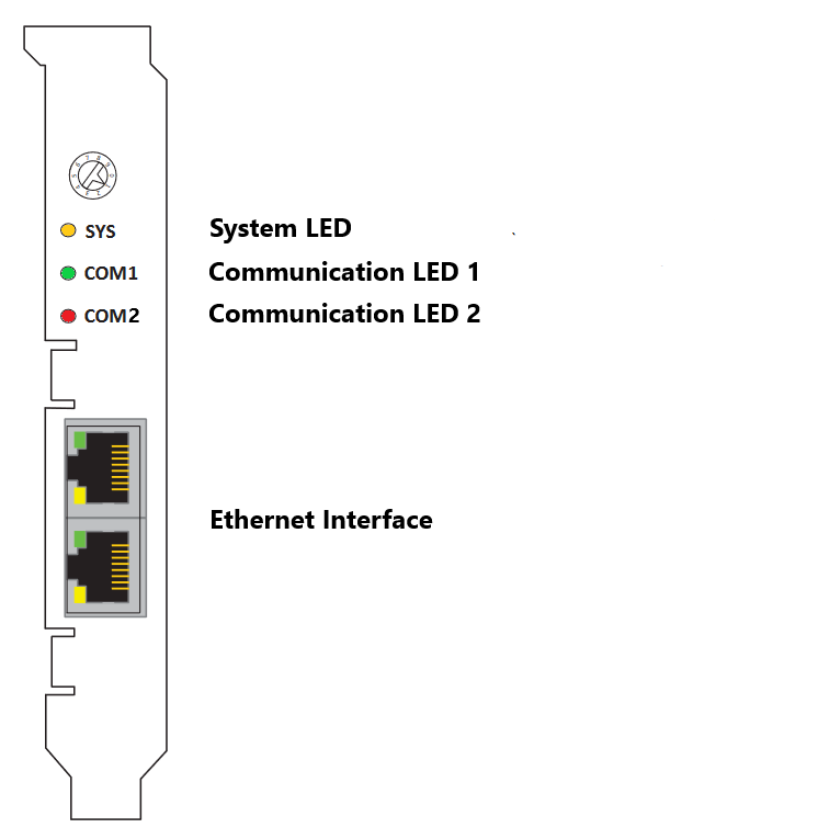
The rotary switch has no functional role.
IO755 mPCIe module
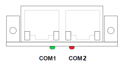
Note that in some real-time target machines,
the mPCIe module is reversed; that is, the Error LED appears on the right.
LED Status Description
Note that only the IO755 PCI and PCIe modules have the SYS LED. This LED does not
feature on the IO755 mPCIe module.