IO753 Usage Notes
IO753 Usage Notes — Usage information about the
I/O module
Description
This section describes how to configure the Modbus TCP network.
SYCON.net Configuration Tool
![[Note]](images/note.png) | Note |
|---|
Only SYCON.net V1.400 Build 170125 has been
tested. There is no guarantee therefore that other versions will work with the
Speedgoat I/O Blockset. |
For some advanced scenarios the Modbus TCP Client may need to be configured with
the SYCON.net configuration tool.
Open SYCON.net and locate the "CIFX RE/OMB" device. Drag and drop the
device to the main panel.
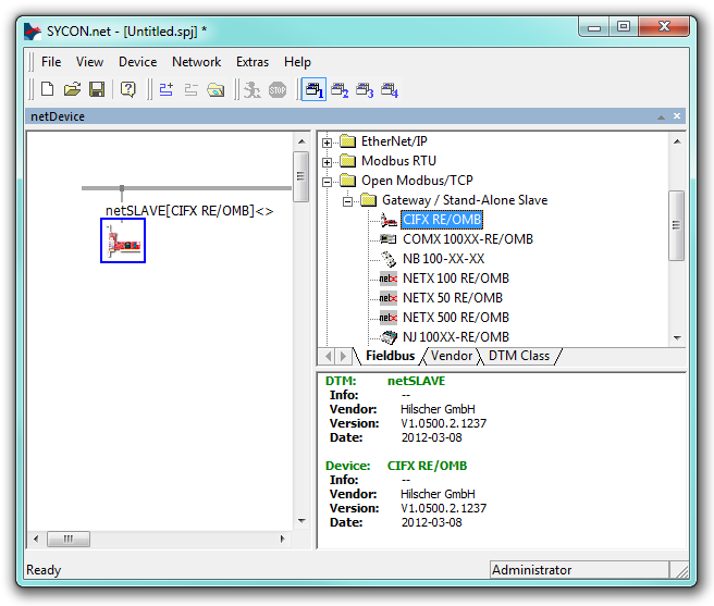
Double-click on the icon to open the Configuration window of the
controller.
Navigate to Configuration, Configuration. These are the parameters that
you can use to setup the network settings of the Modbus TCP Client.
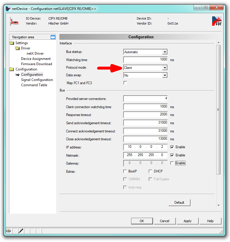
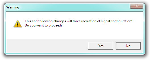
For the Modbus TCP Client it is important to change the parameter
"Protocol mode" from "I/O Server" to "Client" and confirm the popup window
with yes.
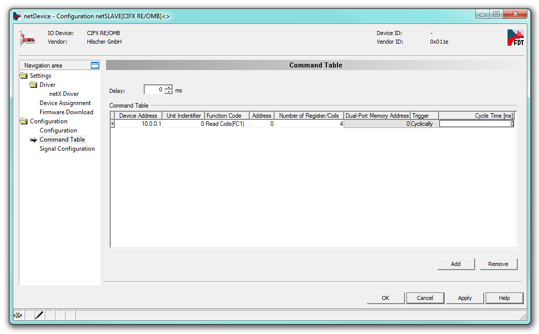
Navigate to Configuration, Command Table. Here you can setup the Modbus
TCP command table.
| Note |
|---|
The maximum number of configurable Modbus TCP servers is 16. |
Apply the configuration and close the windows. Right click on the
controller icon and select Additional Functions, Export, DBM/nxd.
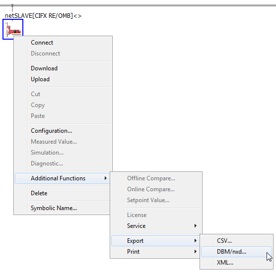
Select a name for the file, e.g.: my_client.nxd and save the file.
In MATLAB, locate the file and use the following script to load the
configuration to the target machine.
IO753                 = sg_IO75X_struct();           % Define default structure

IO753.protocol        = 'IO753';                     % Protocol Speedgoat ID
IO753.cardid          = '1';                         % Card ID as defined in the model
IO753.configfiles     = '2';                         % Number of configuration files
IO753.configPath      = 'C:\Tests\ModbusTCP';        % Absolute file path or '' for current directory
IO753.configfile1     = 'my_client.nxd';             % Name of first configuration file
IO753.configfile2     = 'my_client_CmdTbl.nxd';      % Name of second configuration file

sg_IO75X_loadconfig(IO753);
Configure the driver blocks according to the configuration defined in
SYCON.net. In the Setup driver block select "Configuration mode:
Configuration file".
When you build the model, the firmware and configuration are loaded to the
IO753 Modbus TCP Client I/O module.
Front Plate Description
IO753 PCI and PCIe modules
The IO753 acts as one Modbus TCP Client exclusively. The two RJ45 connectors
simply serve to build up a line-based network structure. Plug the cable from the
previous Modbus TCP Server into the first socket. Connect the second socket with
the next Modbus TCP Server. The LEDs described below indicate the communication
status of the single Modbus TCP Client.
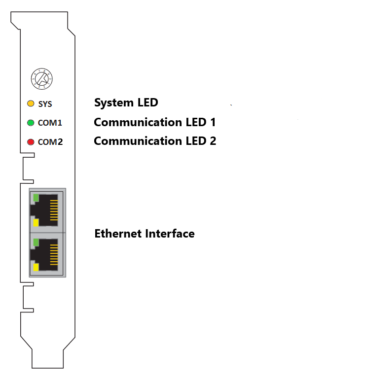
The rotary switch has no functional role.
IO753 mPCIe module
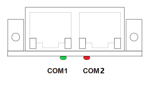
Note that in some real-time target machines,
the mPCIe module is reversed; that is, the Error LED appears on the right.
LED Status Description
Note that only the IO753 PCI and PCIe modules have the SYS LED. This LED does not
feature on the IO753 mPCIe module.