General
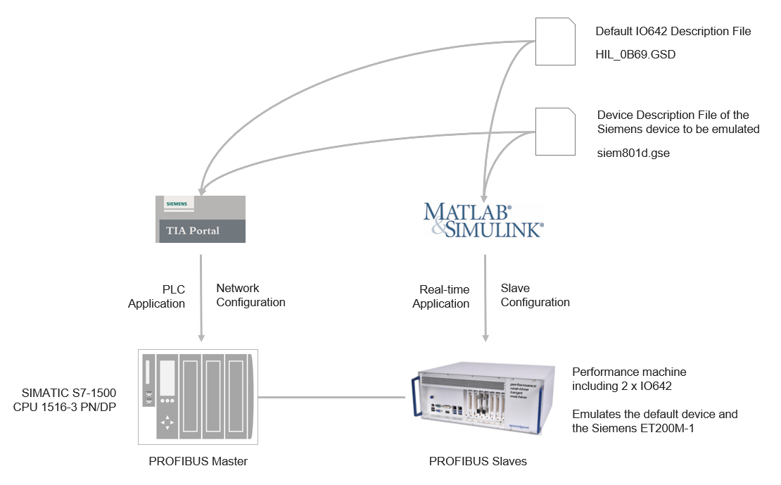
The network contains a Siemens PLC acting as a master and a Speedgoat
Performance real-time target machine with two IO642 PROFIBUS Slave modules.
Slave 1 is configured as the default device. Slave 2 emulates a Siemens ET
200M-1. In a real plant, such a device is referred to as a bus coupler with a
backplane bus where the user can plug hardware modules like analog and digital
modules whose data is mapped to the PROFIBUS network.
The Siemens software TIA Portal is used to configure and program the
PLC.
Master Side
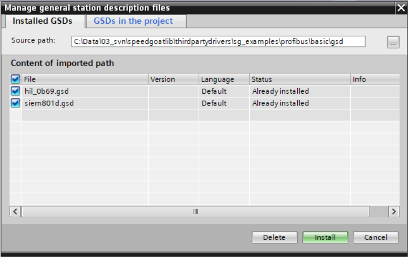
In the TIA portal, click Options -->
Manage General Station Description Files
(GSD). Navigate to the folder where the GSD files of both slaves
are stored. Select both rows and click Install.
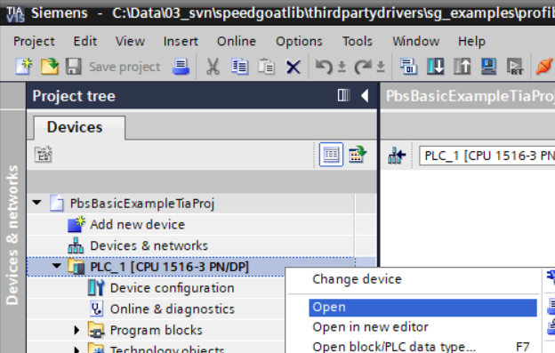
In the project tree right-click the PLC node and select Open. The Hardware Configuration opens.
Switch to the Network view and open the
Hardware catalog.
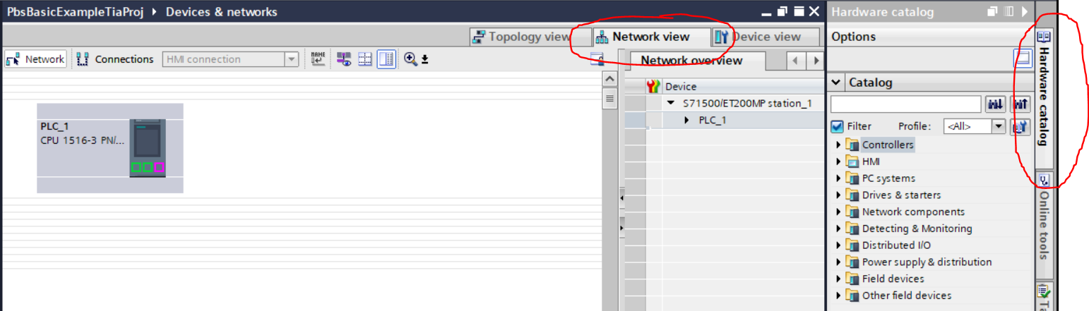
Drag both slave nodes from the hardware catalog to the network canvas.
Connect the PROFIBUS port of each slave with the port of the master.
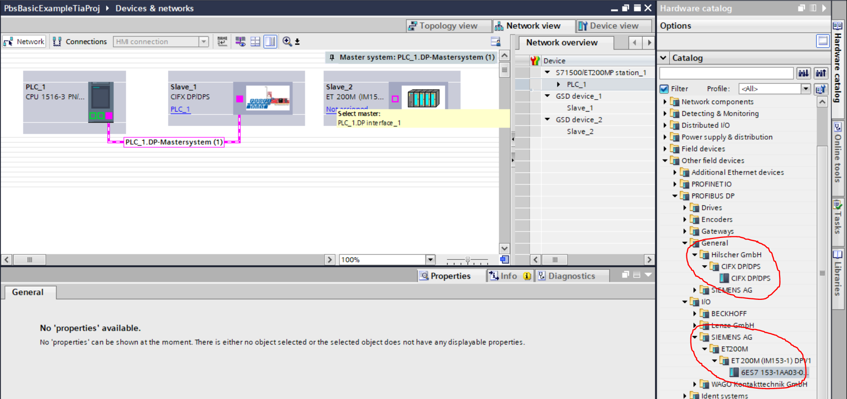
Right-click the connection line and select Properties. Adjust the PROFIBUS timing if necessary.
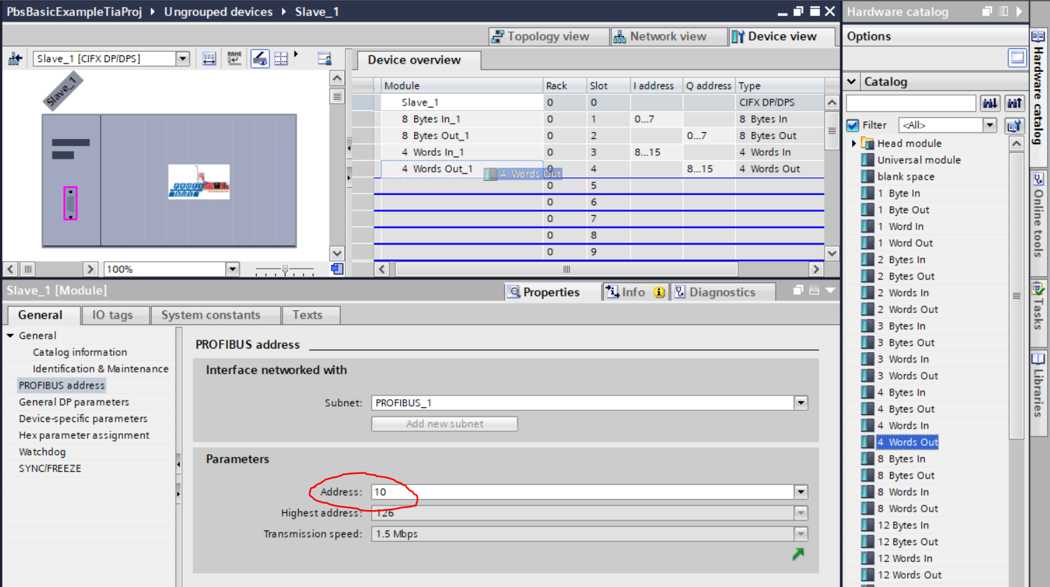
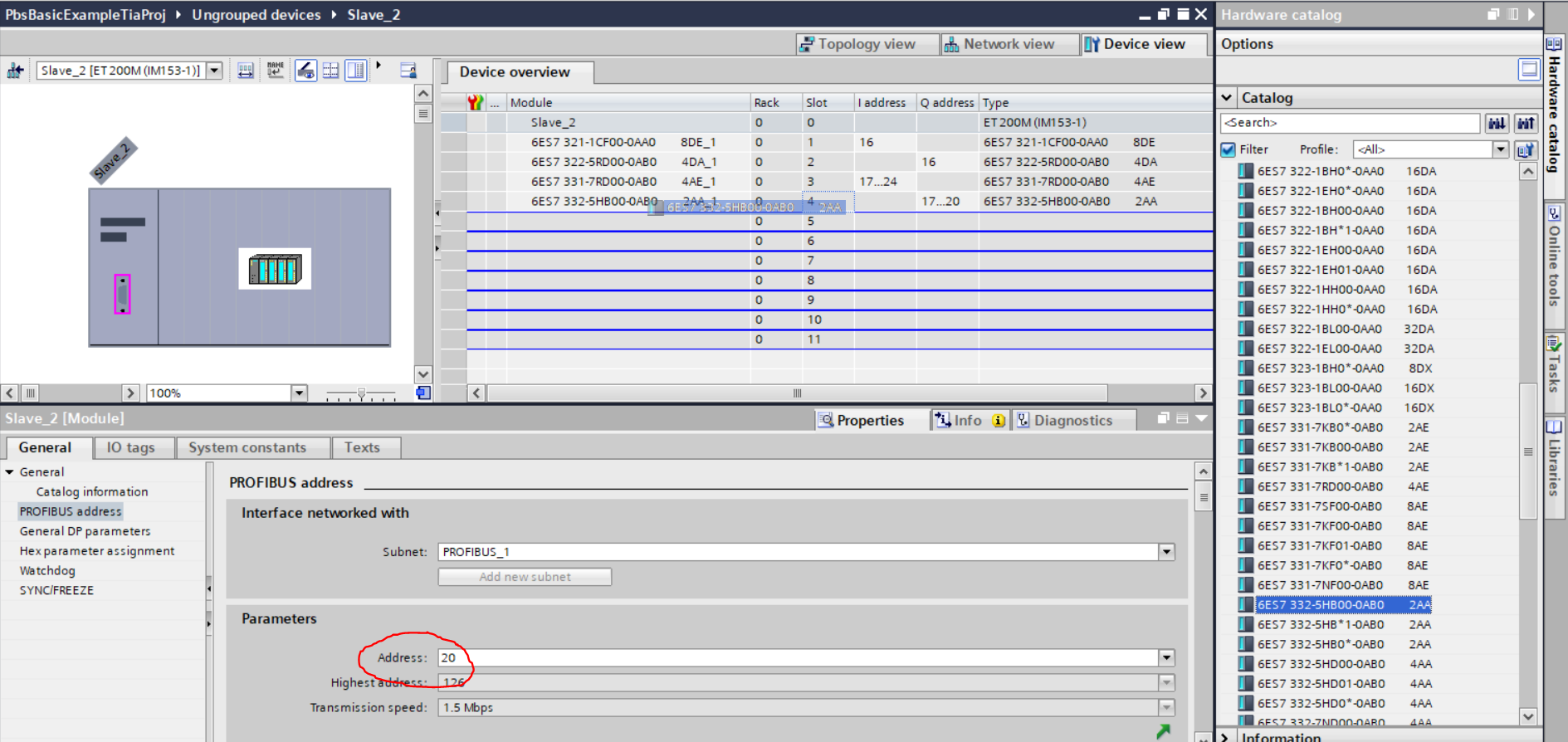
Select a slave and switch to the Device
view. Open the Properties window and
enter the correct PROFIBUS address. Drag and drop the desired I/O data modules
from the hardware catalog to the module table of the slave. This table shows the
structured content of the payload of the cyclic frames the master exchanges with
the slave. When the connection is being established, the PROFIBUS master sends
this information to the slave and the slave checks if the module configuration
matches the expected configuration. The Speedgoat IO642 PROFIBUS slave is
special because it always accepts the module configuration and updates its
internal registers.
Furthermore, the module table helps you to calculate the overall length of I/O
data of a slave. You need this information to configure the input and output
data length of the IO642 send and receive blocks.
Slave_1
Input length (RX Master, TX Slave): 16 bytes
Output length (TX Master, RX Slave): 16 bytes
Slave_2
Input length (RX Master, TX Slave): 9 bytes
Output length (TX Master, RX Slave): 5 bytes
Furthermore the module table shows the addresses of the I/O data modules
within the memory of the PLC. You need this information to define variables for
your PLC program.
In the project tree right-click PLC tags and
add a new tag table. Define variables which point to the addresses of the
PROFIBUS slave I/O modules.
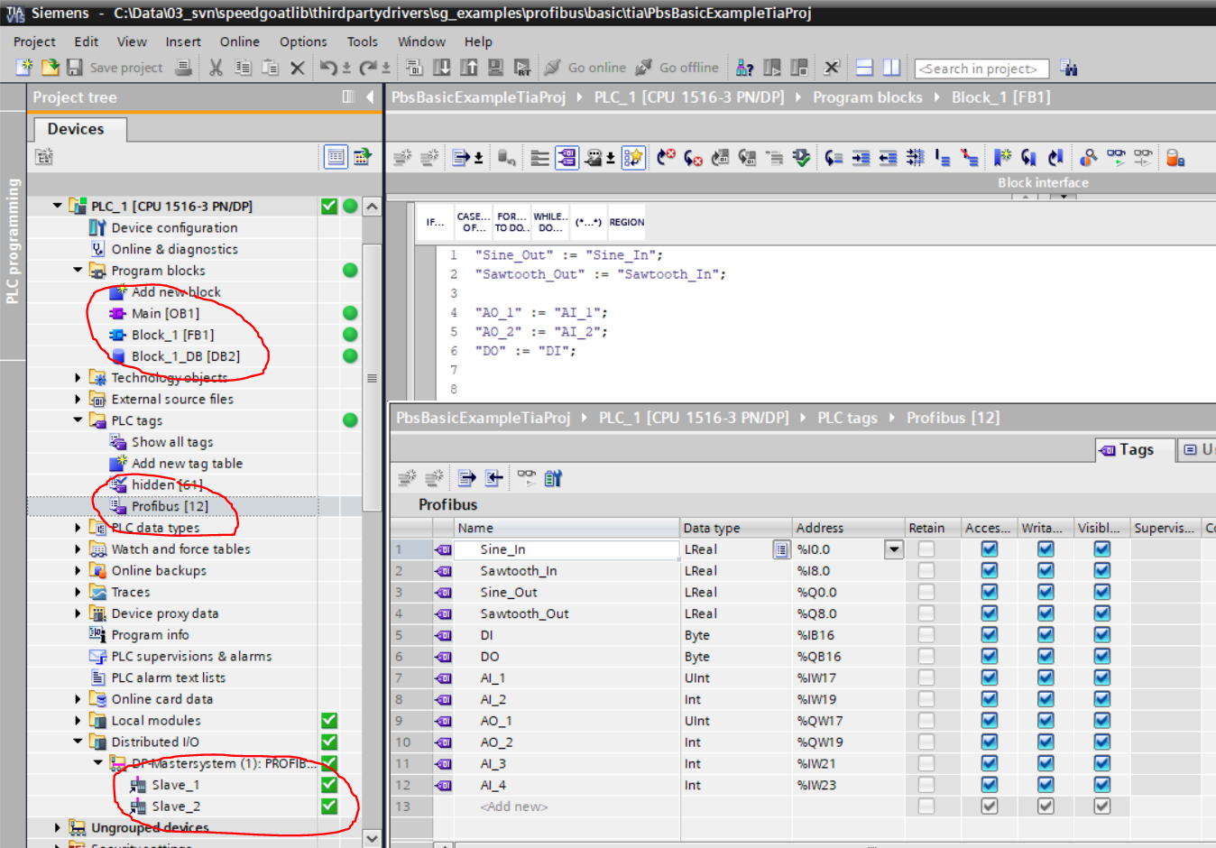
Finally, write your application code. Manage the code in the project tree in
the Program blocks folder. The PLC application
of this example only sends back the data the master receives from the slaves.
In the project tree right-click the PLC node and use the compile and download
commands to run the application on the PLC.
In the Distributed I/O folder you can check
the connection status of the PROFIBUS slaves.
Slave Side
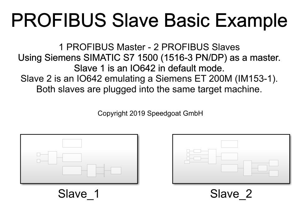
In the Simulink model you need one Setup, one Receive and one Send block for
each Slave respectively. In each Setup block, import the related GSD file and
set the correct PROFIBUS address (the same as in the TIA project).
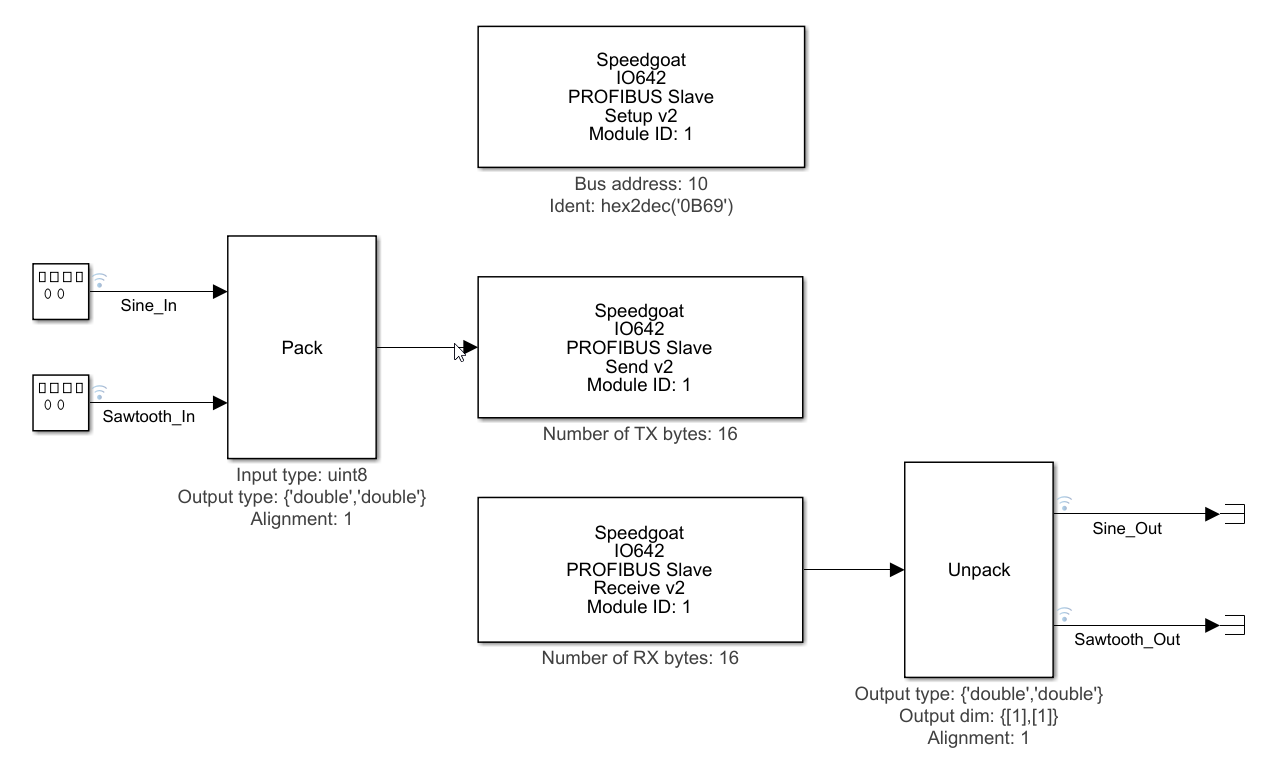
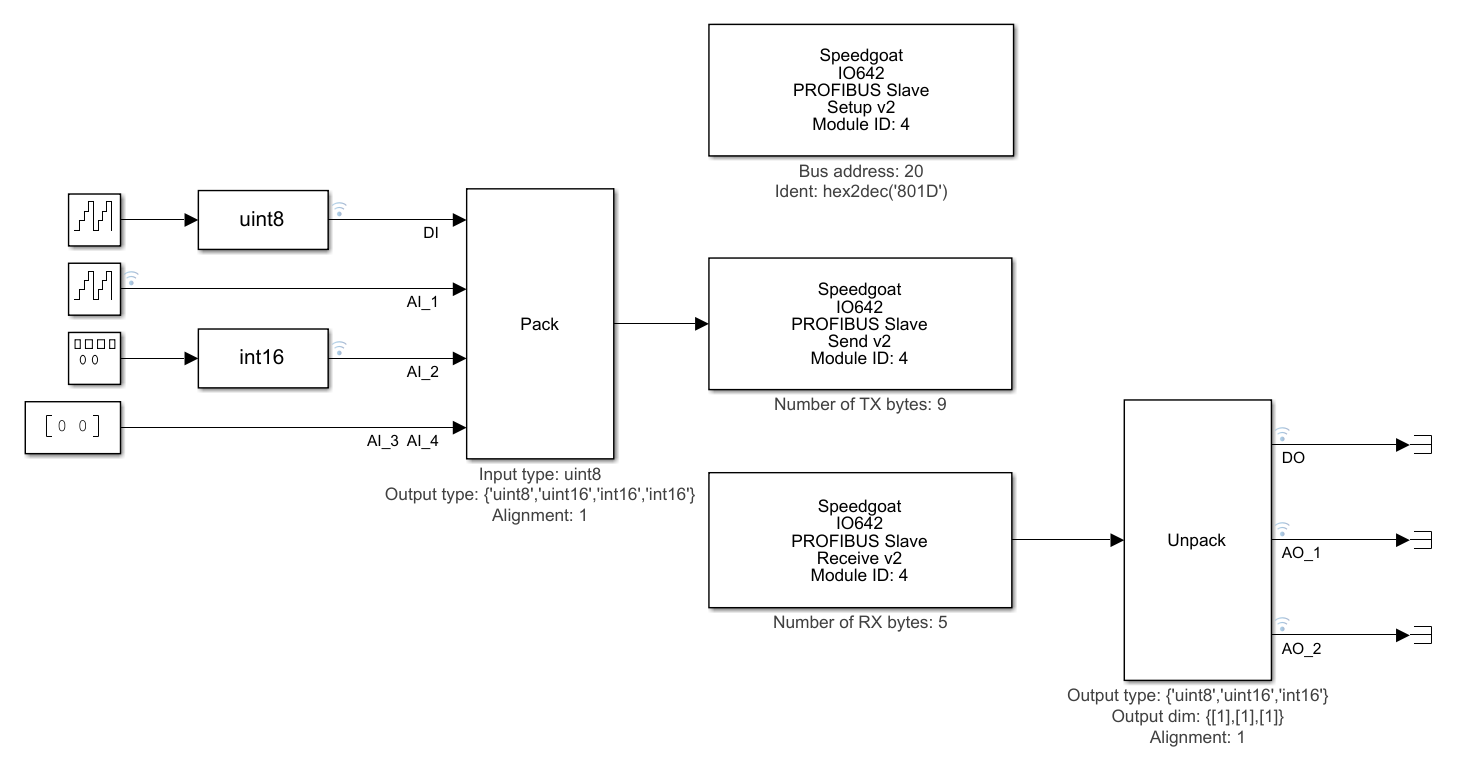
In the Send block enter the length of the data you would like to write to the
TX buffer of the IO642 PROFIBUS slave module. In the Receive block enter the
length of the data you would like to read from the RX buffer of the IO642
PROFIBUS slave module. Reading and writing is performed in relation to the
parameter Sample time. The bus cycle time specified in TIA must not match the
Sample time in the Send and Receive blocks. The IO642 has an internal triple
buffer which guarantees consistent data exchange between the protocol side and
the application side running at different rates.