IO425 - Write
IO425 - Write — Writes the IO425 LVDT/RVDT/Resolver
outputs
Library
Simulink Real-Time - Speedgoat
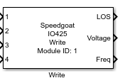
Description
Your model can only contain one of these blocks for each I/O module in your target
machine.
Ports
Inputs
-
X (X is the LVDT/RVDT/Resolver channel number)
The position in percent (-100 to 100) for LVDT/RVDT or in degrees for
resolvers (0° to 360°).
-
In Ctrl
Controls the input relays for all enabled channels by setting the
corresponding element of the vector. Each element of the vector controls
one channel's input relays where each relay can be controlled by its
bit-position. The value '1' closes the relay and '0' opens it. Refer to
the IO425 usage notes for
more information.
-
Out A Ctrl
Controls the output relays of the A output for all enabled channels by
setting the corresponding element of the vector. Each element of the
vector controls one channel's A output relays where each relay can be
controlled by its bit-position. The value '1' closes the relay and '0'
opens it. Refer to the IO425 usage notes for
more information.
-
Out B Ctrl
Controls the output relays of the B output for all enabled channels by
setting the corresponding element of the vector. Each element of the
vector controls one channel's B output relays where each relay can be
controlled by its bit-position. The value '1' closes the relay and '0'
opens it. Refer to the IO425 usage notes for
more information.
All input ports are vectors. The width of the vector and the order of the
corresponding channels depends on the configuration of the Channel Setup.
Outputs
-
LOS
This shows if the excitation input signal is lost (1) or not (0). The
LOS output is active if the input signal is less than 50 %.
-
Voltage
Outputs the measured voltage of the excitation input signal.
-
Frequency
Outputs the measured frequency of the excitation input signal.
-
Position
Outputs the current position being simulated by the module.
All output ports are vectors. The width of the vector, and the order of the
corresponding channels, depends on the configuration of the Channel Setup.
Parameters
-
Module ID
This ID defines the link to the corresponding Setup block
-
Sample Time
Defines the base sample time at which this driver block gets its sample hit. This
parameter can also be set to -1 for inherited
sample time. The units are in seconds.
- Show LOS
Select whether the LOS output should be available.
- Show Input Voltage
Select whether the input voltage output should be available.
- Show Input Frequency
Select whether the input frequency output should be available.
- Show Wrapped Position
Select whether the wrapped position output should be available.
- Enable Input Control
Select whether the input relays' control input should be
available.
- Enable Output A Control
Select whether the output A relays' control input should be
available.
- Enable Output B Control
Select whether the output B relays' control input should be
available.