IO292 - Setup
IO292 - Setup — Configure the IO292 input/output
blocks
Library
Simulink Real-Time - Speedgoat
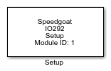
Description
Your model can contain only one Setup block
for each I/O module in your target machine.
Ports
This driver block has no input or output ports.
Parameters
The two tabs of the Setup mask contain all the configuration settings of the IO292
I/O module.
Main Tab
-
PCI Slot (-1: auto-search)
There are two approaches for mapping this block to a specific I/O module installed
in your target machine. All modules of the same type must be configured using the
same method.
Auto-Search: with the default value -1 the I/O module will be automatically located in the
target machine. If you have multiple modules of the same kind, the
Module ID defines which module is associated with this block. To see how
each I/O module maps to a Module ID, use this Speedgoat API:
speedgoat.getIoInterfaces("TargetName", "mySpeedgoat")
Explicit Addressing: to explicitly define the logical address of the
I/O module in the target machine, you can provide the PCI bus and slot
numbers as a vector: [bus, slot]. To determine these numbers, run the
following command in the MATLAB command window:
speedgoat.getIoInterfaces("TargetName", "mySpeedgoat", "Advanced", true)Note
that the PCI address can change whenever an I/O module is added or
removed – usually, auto-search is the best option.
-
Module ID
The Module ID has two functions:
It defines the logical connection between the Setup block and its I/O
blocks
It also informs the auto-search feature of the PCI Slot parameter. If
only one I/O module of this type is installed, the Module ID must be set
to 1. If n modules are installed, it
must be in the range 1:n. Not all the I/O modules installed in the
target machine need to be used. To see how each I/O module maps to a
Module ID, use this Speedgoat API:
speedgoat.getIoInterfaces("TargetName", "mySpeedgoat")
Digital I/O Tab
There are a total of 24 digital I/O channels. These are organized into three
banks (A, B and C) and can be configured as inputs or outputs in groups of
eight, with the exception of bank C (I/O channels 17-24) which can be split into
two groups of four I/O lines. All the channels are configured as inputs at
power-up or after module reset.
-
Active Output Channels
Select the active output channels in a vector. A defined number of channels can be
selected using square brackets, for example, [1 2 3]. A sequence of channels can be
selected using a colon, for example, 1:4.
-
Initial Values
Define the initial signal level present on the outputs after the application has
been downloaded. The values can be set individually by entering a vector: the value
at a certain position in the Initial Values vector
is applied to the channel as defined in the enabled channels. A scalar value applies
to all the channels; for example, for individual values, type "[1 0 0 1]", and to
set all channels to zero, type "0".
-
Reset to Initial Values
Define whether the initial values are also applied once the application has
stopped. The behavior can be set individually for each channel using a vector. A
scalar value applies to all the channels; for example, for individual values, type
"[1 0 0 1]", and to set all channels to zero, type "0". "1" means use the Initial
Value and "0" means keep the latest value.
-
Active Input Channels
Select the active input channels in a vector. Check the active output channels to
avoid conflicts.