IO203 - Setup v2
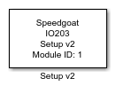
IO203 - Setup v2 — Configure the IO203 read/write v2
block
Library
Simulink Real-Time - Speedgoat
Description
Your model can contain only one Setup block
for each I/O module in your target machine.
Ports
This driver block has no input or output ports.
Parameters
Module setup Tab
-
Module ID
The Module ID has two functions:
It defines the logical connection between the Setup block and its I/O
blocks
It also informs the auto-search feature of the PCI Slot parameter. If
only one I/O module of this type is installed, the Module ID must be set
to 1. If n modules are installed, it
must be in the range 1:n. Not all the I/O modules installed in the
target machine need to be used. To see how each I/O module maps to a
Module ID, use this Speedgoat API:
speedgoat.getIoInterfaces("TargetName", "mySpeedgoat")
-
PCI Slot (-1: auto-search)
There are two approaches for mapping this block to a specific I/O module installed
in your target machine. All modules of the same type must be configured using the
same method.
Auto-Search: with the default value -1 the I/O module will be automatically located in the
target machine. If you have multiple modules of the same kind, the
Module ID defines which module is associated with this block. To see how
each I/O module maps to a Module ID, use this Speedgoat API:
speedgoat.getIoInterfaces("TargetName", "mySpeedgoat")
Explicit Addressing: to explicitly define the logical address of the
I/O module in the target machine, you can provide the PCI bus and slot
numbers as a vector: [bus, slot]. To determine these numbers, run the
following command in the MATLAB command window:
speedgoat.getIoInterfaces("TargetName", "mySpeedgoat", "Advanced", true)Note
that the PCI address can change whenever an I/O module is added or
removed – usually, auto-search is the best option.
-
Enable 5V TTL output level
Enable 5V output level instead of 3.3V. In addition, the jumper J1 on
the I/O module must be set correctly.
Channels Setup Tab
-
Use Checkboxes for I/O Direction
Select this option to use the matrix of checkboxes
"Checkboxes channels configuration" to define
the direction of the digital channels, or clear it to define it with the
"Direction Vector".
-
Direction vector
Warning: To use this field, also
in remote with set_param(), be sure that "Use Checkboxes for
I/O Direction" is off.
When the "Use Checkboxes for I/O Direction" is
not selected (cleared), the
direction of the digital channels is configured with a vector of 64
elements of the type doubles, where the index number corresponds to the
channel number. The value "0" defines
the channel as Input, and the value "1"
defines the channel as Output.
When the "Use Checkboxes for I/O Direction"
is selected, this field
is updated with the configuration used in the "Checkboxes
channels configuration", and it can not be
modified.
-
Checkboxes channels configuration
When the "Use Checkboxes for I/O Direction" is
not selected (cleared), this matrix
of checkboxes is used to represent the "Direction
vector", and it can not be modified.
When the "Use Checkboxes for I/O Direction"
is selected, this field is used to
define the direction of each channel. As indicated in the Legend, when
the channel's checkbox is cleared
the channel is set to Input, and when
the channel's checkbox is selected
the channel is set to Output. The new
configuration is then also represented in the deactivated field
"Direction Vector". The "Toggle all"
button takes the state of the first checkbox, and assign to
all the channels the opposite state.
-
Reset vector
This field specifies the behaviour of the channels at model
termination. Enter a scalar or a vector of the same length as the
channel vector. If a scalar value is specified, its value will be used
for all channels. A value of 1 causes the corresponding channel to be
reset to the value specified in the 'Initial value vector' field. A
value of 0 causes the channel to remain at the last value used while the
model was running.
-
Initial value vector
This field specifies the initial value of the channel after the model
is downloaded. Enter a scalar or a vector of the same length as the
channel vector. If a scalar value is specified, its value will be used
for all channels. A value of 1 causes the corresponding channel to
output a high-level, 0 a low-level.