IO109 - Analog input (DMA)
IO109 - Analog input (DMA) —
Reads the IO109 analog inputs (DMA)
Library
Library: Simulink Real-Time - Speedgoat
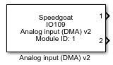
Description
This driver block can be used to acquire frame-based analog input signals from the
IO109 I/O module.
In contrast to most other Speedgoat I/O modules, there is no Setup block available
for the IO109.
Ports
This driver block has, depending on the "Output port dimensions" parameter, either
one output port for each channel (when set to "Vectors") or a single output port
(when set to "Matrix") returning the acquired analog input frames.
Each port (signal) returns the analog value in volts or the raw ADC data.
Outputs (when "Output port dimensions" is set to "Vectors")
-
X (X is the analog channel number)
The value from analog channel X in volts or the raw ADC data.
Data Type:
double (when returning voltage values) or
int32 (when returning ADC values)
Outputs (when "Output port dimensions" is set to "Matrix")
-
Output
A matrix of the "frame size" x "selected channels" size, containing
the values of the corresponding analog channel in volts or the raw ADC
data.
Data Type:
double (when returning voltage values) or
int32 (when returning ADC values)
Parameters
The two tabs of the analog input parameter dialog box contain the IO109 I/O module
configuration settings.
Main Tab
-
Module ID
A unique module ID must be used for each IO109 Analog input block in
your model.
The module ID has an impact on the PCI slot auto-search feature: if
only one I/O module is installed, the module ID must be set to 1. If
multiple modules are installed, it must be in the range 1:n. Not all the
I/O modules installed in the target machine need to be used.
-
PCI Slot (-1: auto-search)
There are two approaches for mapping this block to a specific I/O module installed
in your target machine. All modules of the same type must be configured using the
same method.
Auto-Search: with the default value -1 the I/O module will be automatically located in the
target machine. If you have multiple modules of the same kind, the
Module ID defines which module is associated with this block. To see how
each I/O module maps to a Module ID, use this Speedgoat API:
speedgoat.getIoInterfaces("TargetName", "mySpeedgoat")
Explicit Addressing: to explicitly define the logical address of the
I/O module in the target machine, you can provide the PCI bus and slot
numbers as a vector: [bus, slot]. To determine these numbers, run the
following command in the MATLAB command window:
speedgoat.getIoInterfaces("TargetName", "mySpeedgoat", "Advanced", true)Note
that the PCI address can change whenever an I/O module is added or
removed – usually, auto-search is the best option.
-
Trigger Mode
Initiator mode uses the internal clock, and target mode requires a
compatible clock connected to the corresponding input pins.
-
External Sync Logic Level
Defines which kind of electrical signal is used on the EXT CLK/SYNC
input and output pins.
-
Enable Multiboard Sync
If selected, the module will generate a sync pulse on the "EXT SYNC
OUT" pins. This option is only available if the module is configured as
an Initiator (refer to "Triggering Mode").
If you want to synchronize multiple IO109 I/O modules, then set this
option and connect the "EXT SYNC OUT" pins of this module to the "EXT
SYNC INP" pins of the target modules. You can use the "EXT SYNC OUT"
pins of the target modules to link even more targets together. However,
this will introduce a small propagation delay.
The sync pulse will be sent on the second sample hit of the model.
Before that, the modules will not be synchronized.
You do not need to enable this option when clocking an IO107/IO108 I/O
module.
-
Enable Manual Sync Port
If selected, the Analog input block will get a new input port, which
can be used to manually synchronize the I/O module with an external
clock source. This option is only available if the module is configured
as a target (refer to "Triggering Mode").
If you want to clock and synchronize an IO109 I/O module with an
external clock source (for example with an FPGA), then you need to go
through the sync cycle manually. The external source needs to provide
the clock at the "EXT CLK INP" pins of this module and the sync pulses
at the "EXT SYNC INP" pins. You can use the "EXT SYNC OUT" pins of the
target modules to link even more targets together. However, this will
introduce a small propagation delay.
The sync cycle is as follows:
Set the manual sync port "S" of the Analog input block to
0
Send a sync pulse on the "EXT SYNC INP" pins
Set the manual sync port "S" of the Analog input block to
1
Send a sync pulse on the "EXT SYNC INP" pins
The IO109 I/O module is now synchronized with the external
clock and sync source.
You do not need to enable this option when using an IO109 I/O module
as the initiator.
Analog Input Tab
-
Active Channels
Select the active input/output channels in a vector. A defined number of channels
can be selected using square brackets, for example [1 2 3]. A sequence of channels
can be selected using a colon, for example, 1:4.
-
Input Range
Select the voltage range for all input channels: ±2.5 V, ±5
V or ±10 V.
-
Filter
High frequency noise and digital filter images are attenuated by a
2-pole Butterworth lowpass filter, the cut-off frequency of which can be
selected from either of two fixed frequencies.
-
Auto-Calibration at Download
If selected, the module will calibrate itself each time the model is
downloaded to the target.
-
Output Signal
Select whether the output port data will be the measured voltage with
the data type double or a 32-bit signed integer value representing the
raw ADC data.
-
Output Ports
Select how to structure the output ports:
"One port per channel" generates a separate output port for
each channel. Every port outputs a vector where the length
corresponds to the given frame size
"One port for all channels" generates a single output port
which outputs a 2D matrix, where the number of rows is equal to
the frame size, and the number of columns is equal to the number
of active channels
-
Output Frame-Based Signals
If this option is selected, then the output ports will not be normal
vectors or matrices but frame-based signals instead. The organization of
the values inside the vectors/matrix will stay the same. However, this
simplifies the use of blocks from the DSP System Toolbox™, which can
work with frame-based data. This option is only usable when the DSP
System Toolbox has been installed. For more information, refer to the
page about Sample- and Frame-Based Concepts.
-
Frame Size
Enter the number of samples in one frame for each channel listed in
the active channels field. The module issues an interrupt each time the
acquisition of one frame is complete. The frame size must be equal to
the product of the sample time and sample rate. Set one of the three
parameters to -1. This parameter will then be calculated
automatically.
-
Sample Rate
Enter the frequency at which the samples are taken in Hertz. This
frequency must be between 2,000 to 20,0000 Hz (2 kHz to
200 kHz).
-
Block Sample Time
Enter the time between frame completions.