EtherCAT SubDevice Emulator - Send
EtherCAT SubDevice Emulator - Send — Transmits data to the EtherCAT
main device via process data object communication (PDO)
Library
Simulink Real-Time - Speedgoat
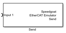
Description
The Send block transmits data to the EtherCAT main device via process data object
communication (PDO). The block does not trigger any communication messages, but
rather copies data to an internal memory holding the data that will be sent to the
main device in the next communication cycle. You can place as many Send blocks in
the model as you wish: one block could transmit a single signal, one block could
transmit all the signals associated with a specific device, and one block could even
transmit the data of all the devices.
![[Tip]](images/tip.png) | Tip |
|---|
Using the createFromEni
function, you can import ENI (EtherCAT Network Information) files and
autogenerate a ready-to-use communication interface. Based on the information
included in the ENI file, the function places the Setup, Send and Receive driver
blocks into the model and automatically sets the block parameters. |
Ports
Inputs
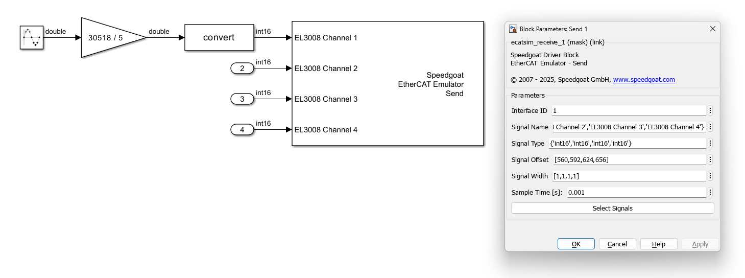
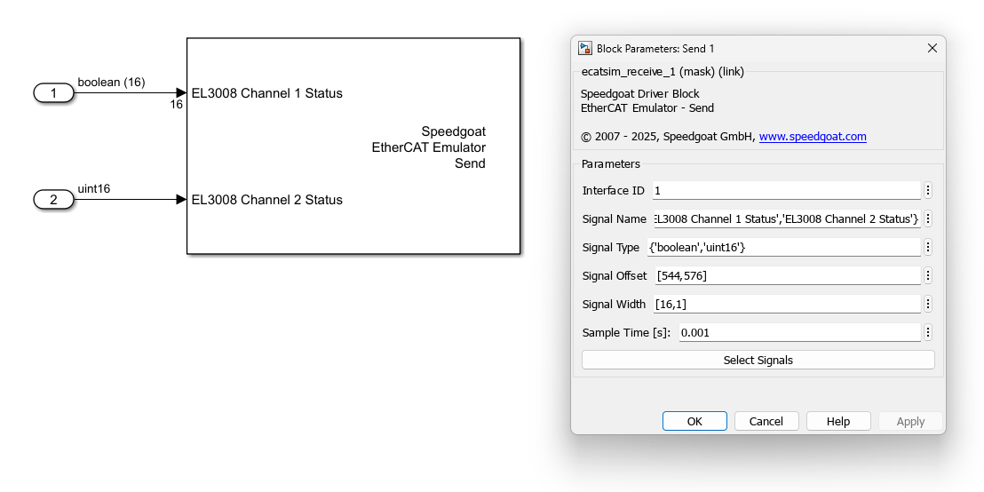
The number of input ports depends on the number of elements defined in
the Signal Type parameter. Each signal
is represented by one input port. The port retrieves its label from the
corresponding element in the Signal
Name parameter, retrieves its data type from the
corresponding element in the Signal
Type parameter, and retrieves its width (vector length)
from the corresponding element in the Signal
Width parameter.
Outputs
This block does not have any output ports.
Parameters
Tab: General
-
Interface ID
Enter the Interface ID of the
corresponding Setup block.
-
Signal Name
Enter the signal names as a cell array of character arrays or strings.
The name is simply used as a label for the port on the block icon and
serves no other purpose. You can find the signal names in the ENI file
and the EtherCAT configuration tool. You can define custom names as
well.
-
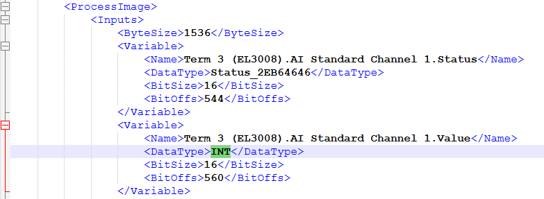
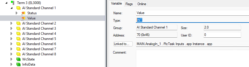
Signal Type
Enter the signal data types as a cell array of character arrays or
strings. You can find the data types in the ENI file and the EtherCAT
configuration tool. Simulink data types and the corresponding IEC61131
types are indicated in the table below. Note that data types entered
here do not affect frame sizes and the EtherCAT communication at all.
The type simply defines the size of the data to be copied from the input
port to the process data area.
-
Signal Offset
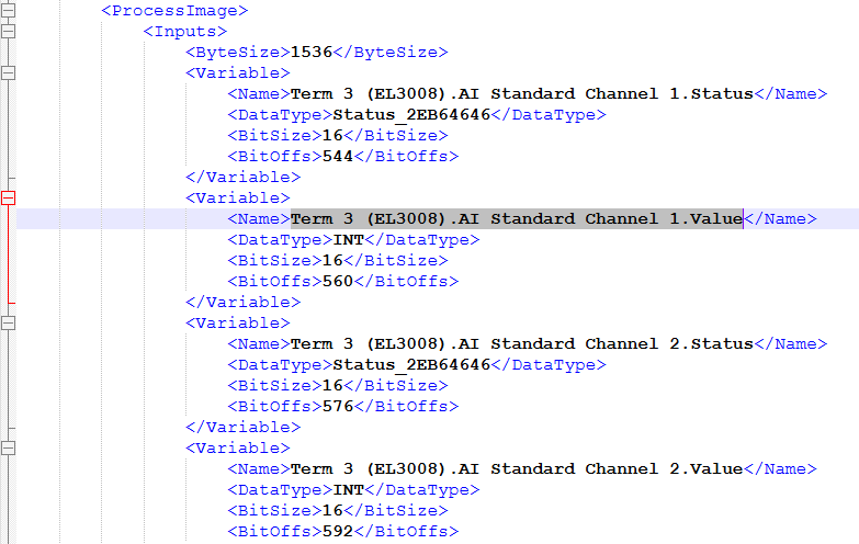
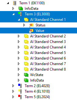
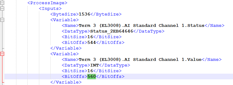
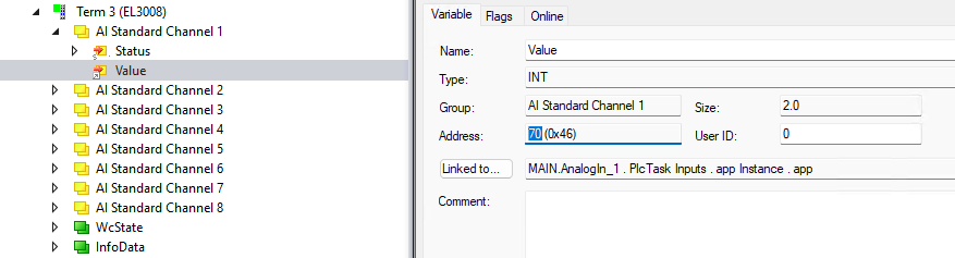
Enter the signal offsets as a numeric vector. An offset is a bit
address in the process data area of the emulator. Offsets are not
relative to the respective subordinate device but absolute over all
subordinate devices. You can find the offset in the ENI file and the
EtherCAT configuration tool. The number in the ENI file is the actual
bit address. The number in the configuration tool might be a pair of
byte and bit addresses. Evaluate the byte address * 8 + bit address to
get the overall bit address (70 * 8 + 0 = 560). Note that offsets
entered here do not affect frame sizes and the EtherCAT communication at
all. The offset simply defines the address in the process data area to
where to copy data.
-
Signal Width
The width parameter determines the number of elements of the input
port. With the default value of 1, the input port expects a scalar
value. With a width greater than 1, the input port becomes a vector. The
width has no corresponding entry in the ENI file. Instead, it serves the
following use cases:
Input signals whose data types do not match fundamental types.
Examples: A custom type of UINT24 is three bytes long and can be
passed as a vector of bytes. Enter 'uint8' in the Signal Type parameter and 3 in the
Signal Width parameter. A
custom type that is 9 bits long can be passed as a vector of
Boolean values. Enter 'boolean' in the Signal Type parameter and 9 in the Signal Width parameter.
Signals that have the same type and are located in the process
data area one after the other without gaps can be passed as a
single vector.
-
Sample Time
Defines the base sample time at which this driver block gets its sample hit. This
parameter can also be set to -1 for inherited
sample time. The units are in seconds.
-
Select Signals
This feature provides an interactive way to configure signal
properties using information from the ENI file. The button opens a
signal selection interface where input signals can be browsed and
selected. After confirmation, signal-specific configuration parameters
are automatically populated in the block.
When the button is clicked, the ENI file path is determined by
checking for a Setup block in the model that uses the same Interface ID. If such a Setup block is found,
the ENI file path is retrieved from the block. If no matching Setup
block is available, or if the ENI path cannot be resolved, a file
selection dialog opens, allowing the user to manually choose the ENI
file.
Once the ENI file has been loaded, a graphical tree browser is
displayed. This browser presents a hierarchical view of EtherCAT
subordinate devices and their input signals as defined in the ENI file.
Devices can be expanded to reveal their input signals. One or more
signals can be selected by marking them directly in the tree. Hold the
CONTROL key to select multiple individual signals. Hold the SHIFT key to
select a range of signals. Selecting a device entry implicitly selects
all its signals.
After confirming the selection by clicking Apply, the relevant properties for each marked
signal—such as signal name, data type, width and offset—are extracted
from the ENI file and written to the corresponding block mask
parameters.