IO752 Usage Notes
IO752 Usage Notes — Usage information about the
I/O module
Description
This section describes how to configure the PROFINET network.
GSDML File
To set up PROFINET communication, you must import the device description files of
PROFINET devices (GSDML file) into your PROFINET controller configuration tool or
PLC programming tool (refer to Step 7). Find the GSDML file of the IO752 PROFINET
Device module here:
>> [speedgoatroot, '\sg_blocks\cifx\eds\GSDML-V2.33-HILSCHER-CIFX RE
                    PNS-20170919.xml']
.
This GSDML file contains multiple Device Access Points. Always select CIFX RE/PNS V3.5.35 - V3.x.
If you use warmstart parameters to simulate a PROFINET device of a different
vendor, you must import the GSDML file of that particular device into your
controller configuration tool. The GSDML file is generally available on the vendor's
website.
I/O Module configuration from Simulink
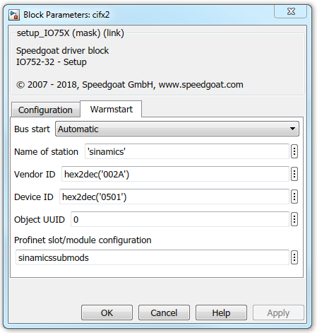
The warmstart mode allows the PROFINET device to be configured in Simulink using
the Setup driver block.
This approach offers more options than Sycon.net and rules out having to generate
and handle configuration files.
Example
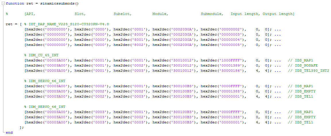
This example shows how to configure an IO752 node which acts as a Siemens
Sinamics CU320-PN with one Control Unit and two drives exchanging data via
Telegram 1.
I/O Module configuration with SYCON.net
During initialization of the real-time application, the IO752 Setup block reads a
configuration file from the hard drive of the target machine and configures the
PROFINET Device protocol stack. Use the SYCON.net configuration tool to create such
a file.
![[Tip]](images/tip.png) | Tip |
|---|
Download the SYCON.net configuration tool from the Speedgoat Customer Portal.
Login to your Speedgoat account. In the Downloads section,
navigate to Software and click SYCON.net (v1.400 Build 170125). |
![[Note]](images/note.png) | Note |
|---|
Only SYCON.net V1.400 Build 170125 has been
tested. There is no guarantee therefore that other versions will work with the
Speedgoat I/O Blockset. |
In addition to this short introduction, please read the SYCON.net help
documentation for detailed information about how to set up a PROFINET device and
export the module configuration file.
Open SYCON.net and locate the "CIFX RE/PNS" device. Drag and drop the
device to the main panel and also add the required PROFINET devices for a
complete fieldbus network configuration.
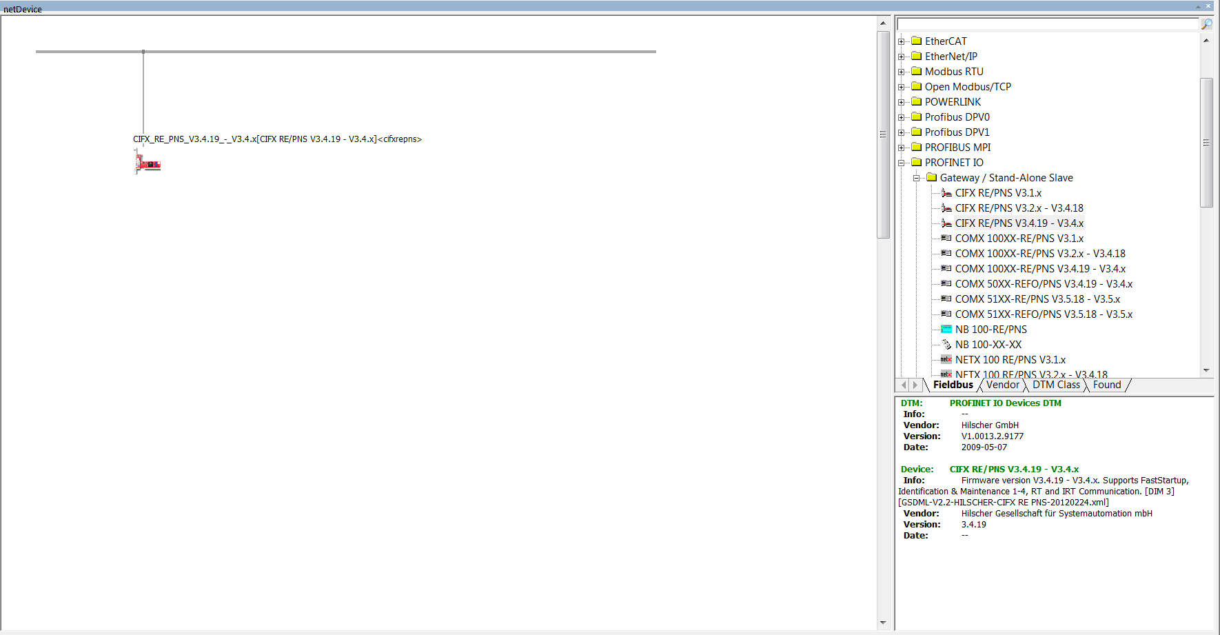
Double-click on the icon to open the Configuration window of the
controller.
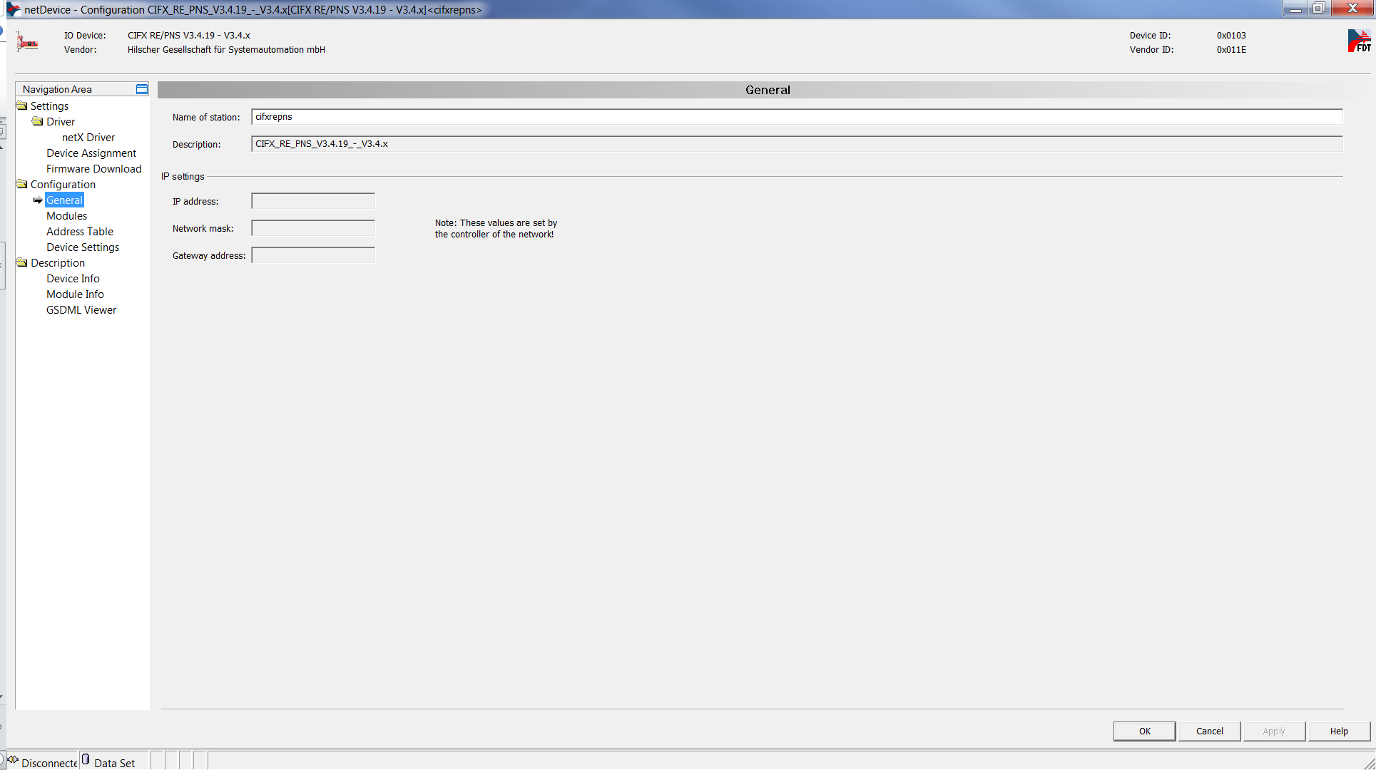
Go to Configuration and then General. These are the parameters that you
can use to setup the PROFINET device name.
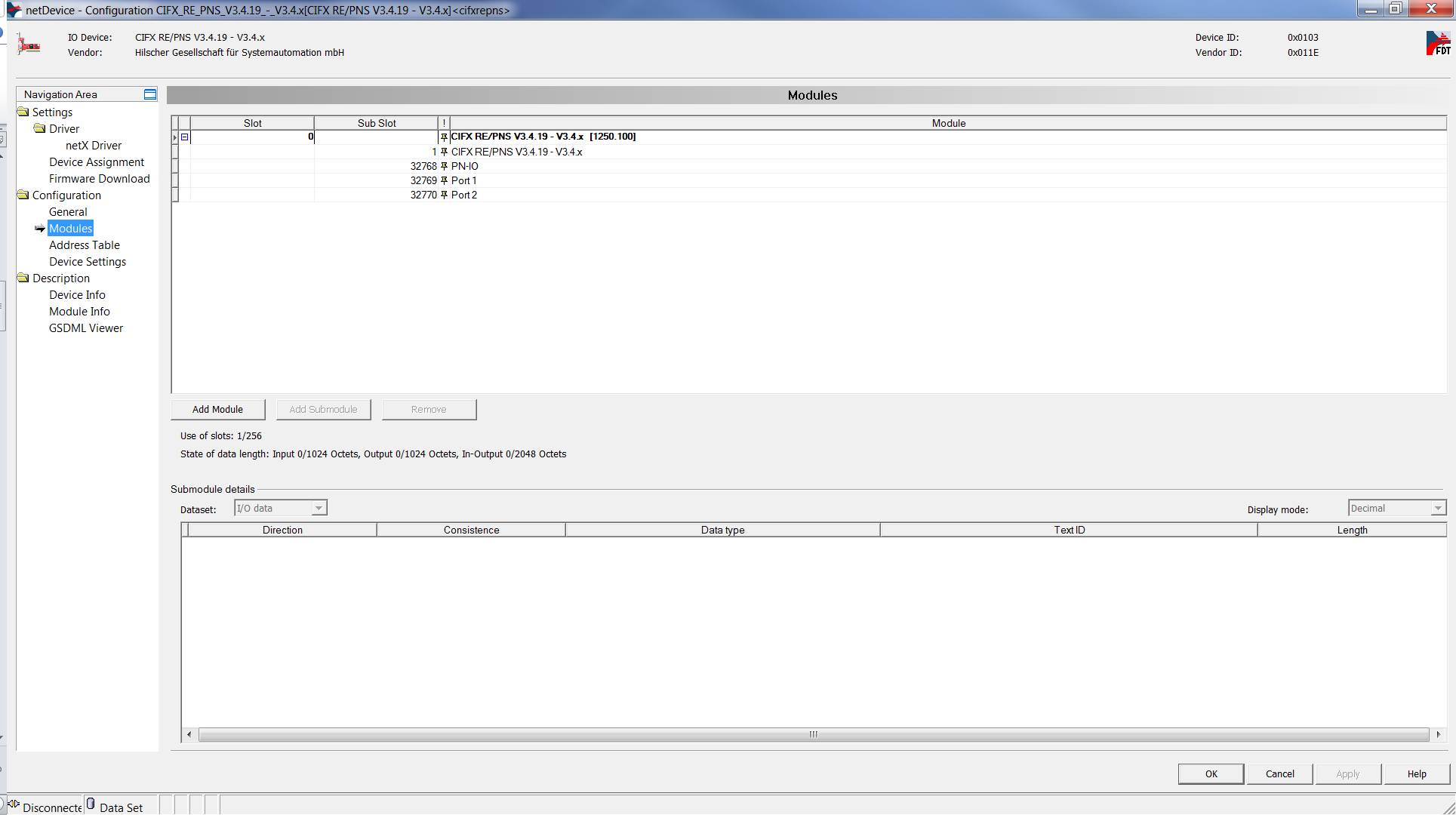
Go to Configuration and then Modules. These are the parameters that you
can use to setup the PROFINET device input and output ports.
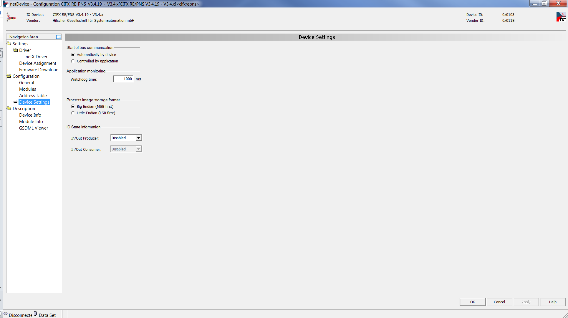
Go to Configuration and then device Settings. These are the parameters
that you can use to setup the PROFINET device.
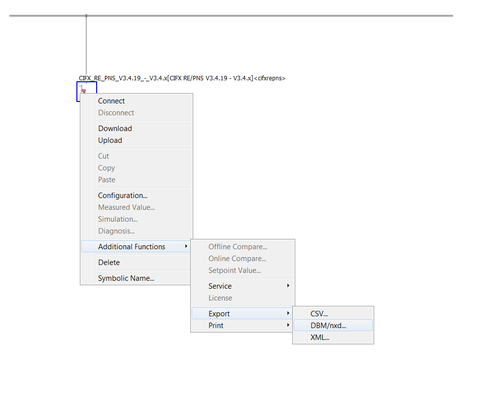
Apply the configuration and close the windows. Right-click on the
controller icon and select Additional Functions, Export and then
DBM/nxd.
Select a name for the file, for example, "my_device.nxd" and save.
In MATLAB, locate the file and use the following script to load the
configuration to the target machine.
IO752             = sg_IO75X_struct();     % Define default structure

IO752.protocol    = 'IO752';               % Protocol Speedgoat ID
IO752.cardid      = '1';                   % Card ID as defined in the model
IO752.configfiles = '2';                   % Number of configuration files
IO752.configPath  = 'C:\Tests\Profinet';   % Absolute file path or '' for current directory
IO752.configfile1 = 'my_device.nxd';       % Name of first configuration file
IO752.configfile2 = 'my_device_nwid.nxd';  % Name of second configuration file

sg_IO75X_loadconfig(IO752);
| Note |
|---|
When using v2 blocks, the protocol must be set to "IO752_V2". |
IO752             = sg_IO75X_struct();     % Define default structure

IO752.protocol    = 'IO752_V2';            % Protocol Speedgoat ID
IO752.cardid      = '1';                   % Card ID as defined in the model
IO752.configfiles = '2';                   % Number of configuration files
IO752.configPath  = 'C:\Tests\Profinet';   % Absolute file path or '' for current directory
IO752.configfile1 = 'my_device.nxd';       % Name of first configuration file
IO752.configfile2 = 'my_device_nwid.nxd';  % Name of second configuration file

sg_IO75X_loadconfig(IO752);
Configure the driver blocks according to the configuration defined in
SYCON.net. In the Setup driver block select "Configuration mode:
Configuration file".
When you build the model, the firmware and configuration are loaded to the
IO752 PROFINET device I/O module.
IRT Mode
Check IRT
Mode how to configure the IRT mode.
Front Plate Description
IO752 PCI and PCIe modules
The IO752 acts as one PROFINET Device exclusively. The two RJ45 connectors
simply serve to build up a line-based network structure. Plug the cable from the
PROFINET Controller or the previous Device into the first socket. Connect the
second socket with the next PROFINET Device. The LEDs described below indicate
the communication status of the single PROFINET Device.
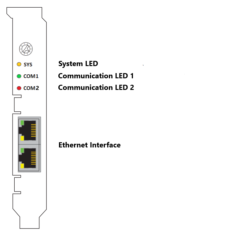
The rotary switch has no functional role.
IO752 mPCIe module
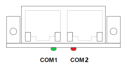
Note that in some real-time target machines,
the mPCIe module is reversed; that is, the Error LED appears on the right.
IO752-32 Multi-node simulator
The IO752-32 simulates 32 PROFINET Device nodes, split into two clusters with
16 protocol chips each. Within a cluster, the nodes represent a line-based
network structure. Build up a combined network by connecting both center
sockets. Each node has two LEDs that indicate the communication status.

LED Status Description
Note that only the IO752 PCI and PCIe modules have the SYS LED. This LED does not
feature on the IO752 mPCIe module and the IO752-32 multi-node simulator.